1.
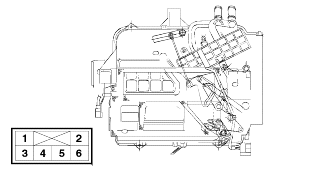
Temperature control actuators are installed in the heater unit case. The control switches and the vent ductswitch will operate actuators to regulatethe temperature and discharge air.

Temperature control actuators are installed in the heater unit case. The control switches and the vent ductswitch will operate actuators to regulatethe temperature and discharge air.

Temp. switch terminal voltage check.
Terminal | Voltage | Remark |
1 | 12V (+,-) | Change Polarity |
3 | 12V (+,-) | Change Polarity |
4 | 5V | Sensor Voltage |
5 | Change with resistance | Variable Resistance |
6 | Ground | Ground |
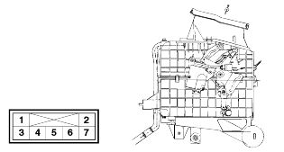
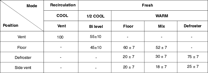
Pressing the mode select switch with the ignition on will shift the driver side and passenger side mode door actuators as follows :
VENT ⇒ BI/LEVEL ⇒ FLOOR ⇒ MIX
Mode actuator circuit diagram and voltage.

Terminal | Description | Voltage |
1 | IG | 12V |
2 | Ground | - |
3 | Vent | 0V |
4 | Bi-level | 12V |
5 | Floor | 12V |
6 | Mix | 12V |
7 | Defroster | 12V |
