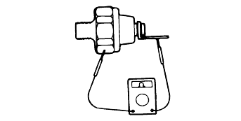
Connect a tester (ohm range) between the terminal and the body of the switch to check for continuity. The switch is normal if there is continuity.If there is no continuity, replace the switch.
The sealant must not get into the thread top surface. Use care not to torque excessively.
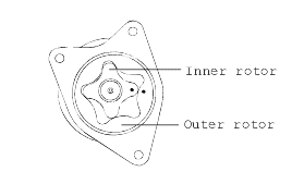
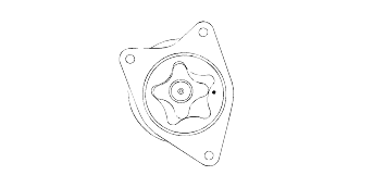
Install the outer and inner gear into the oil pump housing and make sure that they turn smoothly with no excessive play between them.
Check the side clearance (drive gear and drivengear))
: 0.02 - 0.07 mm (0.00078 - 0.0027 in.) |
Check the tip clearance.
Check the radial clearance.
The oil filter mounting surface must be free from damage.
Check for cracks and oil leaks.
Make sure that the relief plunger slides smoothly and the relief spring is not damaged.
Connect a tester (ohm range) between the terminal and the body of the switch to check for continuity. The switch is normal if there is continuity.If there is no continuity, replace the switch.

Insert a thin rod in the oil hole of the switch and push it in lightly. The switch is normal if no continuity is detected (infinite resistance onthe tester). If there is continuity, replace the switch.
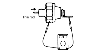
Apply a 0.5 kg/cm² pressure to the oil hole.
The switch is normal if there is no continuity.
Also check for air leaks. If any air leaks are detected, the cause may be a broken diaphragm. Replace the switch if it leaks.
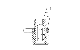
Check the oil jet and check valve for clogging.
Check the oil jet for damage and deformation.
When installing the rotor, be sure to apply engine oil to the entire surfaces of the rotor.
