Has a problem been found?
YES
Repair as necessary and go to "Verification of Vehicle Repair" procedure
NO
Go to " CAN(FL,RL,RRSS) Signal Inspection " procedure.
Many malfunctions in the electrical system are caused by poor harness and terminals. Faults can also be caused by interference from other electrical systems, and mechanical or chemical damage.
Thoroughly check connectors for looseness, poor connection, bending, corrosion, contamination, deterioration,or damage.
Has a problem been found?
YES
Repair as necessary and go to "Verification of Vehicle Repair" procedure
NO
Go to " CAN(FL,RL,RRSS) Signal Inspection " procedure.
Engine : ON
TCCU connector : Connect.
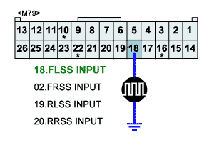
Monitor signal waveform between terminal 02, 18, 19, 20 of TCCU harness connector M79 and chassis ground .
Start and drive vehicle in gear and maintain vehicle speed approx. 10km/h or less(6mph or less)
Specification : Signal Waveform & Data

The above value is only for reference. The actual value may differ from it according to various engine condition.
Is PWN(FL,RL,RRSS) Signal display near the specified value?
YES
Fault is intermittent caused by poor contact in the sensor’s and/or TCCU’s connector or was repaired and TCCU memory was not cleared.Thoroughly check connectors for looseness, poor connection, bending, corrosion, contamination, deterioration, or damage. Repair or replace as necessary and then go to "Verification of Vehicle Repair" procedure.
NO
Go to " PWN(FL,RL,RRSS)comm. Line ground short Inspection " procedure.
Ignition "OFF".
TCCU connector : Disconnect.
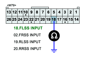
Measure resistance between terminal 02, 18, 19, 20 of TCCU harness connector M79 and chassis ground .
Specification : ∞ Ω

The above value is only for reference. The actual value may differ from it according to various engine condition.
Is resistance display near the specified value?
YES
Go to " CAN(FL,RL,RRSS)comm. Line open Inspection " procedure.
NO
Check for ground to short circuit of CAN(FL,RL,RRSS)comm. Line.
Repair as necessary and then go to "Verification of Vehicle Repair" procedure.
Ignition OFF
TCCU, ABS control module connector : Disconnect.
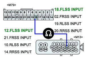
Measure resistance between terminal 02, 18, 19, 20 of TCCU harness connector M79 and terminal 12, 10, 14, 21 of ABS control module harness connector E13 .
Specification : 1Ω below.

The above value is only for reference. The actual value may differ from it according to various engine condition.
Is resistance display near the specified value?
YES
Check for normal operation of "ABS control module" side.
Repair as necessary and then go to "Verification of Vehicle Repair" procedure.
NO
Check for open circuit of PWN(FL,RL,RRSS)comm. Line.
Repair as necessary and then go to "Verification of Vehicle Repair" procedure.