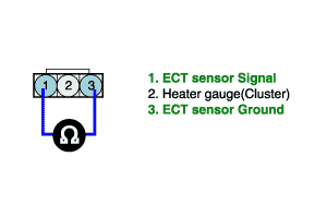
Component Inspection
1.

Check ECTS

(1)

Ignition "OFF"

(2)

Disconnect ECTS connector.

(3)

Measure resistance between terminals 1 and 3 of the ECT sensor (to ECT sensor side).

Specification :Error range is 2~3%

Temperature(℃/℉)

-40/40

-30/-22

-20/-4

0/32

20/68

80/176

100/212

110/230

120/248

Resistance(kΩ)

45.3

25.6

15.1

5.8

2.5

0.33

0.19

0.16

0.13

Voltage(V)

4.48

4.34

4.12

3.46

2.57

0.64

0.39

0.34

0.27

(4)

Is the measured resistance within specifications ?

YES

▶ Go to "Check PCM" as below.

NO

▶ Substitute with a known - good ECTS and check for proper operation.

▶ If the problem is corrected, replace ECTS and go to "Verification of Vehicle Repair" procedure.
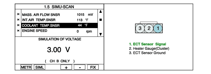
2.

Check PCM

(1)

Ignition "OFF"

(2)

Connect Scantool and Ignition "ON"

(3)

Select simulation function on scantool.

(4)

Simulate voltage at terminal 1 of ECT sensor signal connector.

(5)

Does the signal value of ECT sensor changes according to simulation voltage?

YES

▶ Thoroughly check connectors for looseness, poor connection, bending, corrosion, contamination, deterioration, or damage. Repair or replace as necessary and go to "Verification of Vehicle Repair" procedure.

NO

▶ Substitute with a known - good PCM and check for proper operation.

If the problem is corrected, replace PCM and go to "Verification of Vehicle Repair" procedure.

Яндекс.Метрика