
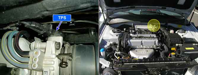
Throttle Position (TP) Sensor measures the opening angle of throttle valve and mounted on the side of the throttle body and is connected to the throttle blade shaft. The TP sensor’s resistance changes according to the throttle blade shaft position. TP Sensor has a potentiometer whose resistance changes along with the Throttle valve position. The Powertrain Control Module (PCM) provides a 5volt reference voltage to the TP Sensor. The PCM reads the voltage across the TP Sensor and converts it into throttle position. During acceleration, the TP Sensor resistance decreases. During deceleration, the TP Sensor resistance increases. The PCM uses the TP Sensor signal to adjust timing and injector pulse width. The TP Sensor signal along with the MAF sensor signal is used by the PCM to calculate engine load. Throttle angle information to the PCM to be used for the detection of engine status such as idle, part load, full throttle, and acceleration fuel enrichment.
If the TPS output voltage is higher than threshold value, the PCM determines that a malfunction exists and a DTC is stored.
Item | Detecting Condition | Possible cause |
DTC Strategy | ● Output voltage is monitored. | ● Poor connection ● Open or short to battery in TPS circuit ● Faulty TPS ● Faulty PCM |
Enable Conditions | ● Load value < 60% | |
● Engine speed < 5000rpm | ||
Threshold value | ● Output voltage > 4.8V(for 4 sec) | |
Diagnosis Time | ● Continuous |
Throttle valve fully closed | 0.3~0.9V |
Throttle valve fully open | 4.3~4.8V |
Throttle valve resistance (terminals 1 and 2) | 3.5~6.5kΩ at 20℃(68℉) |