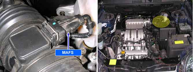
The Mass Air Flow Sensor (MAFS) is located between the air cleaner assembly and the throttle body. The MAFS uses a hot film type sensing element to measure the mass of intake air entering the engine. This hot film type air flow sensor consists of a hot film sensor, housing and metering ducts. Mass air flow rate is measured by detection of heat transfer from a hot film probe. The change in air flow rate causes change in the amount of heat being transferred from the hot film probe surface to the air. A large amount of intake air represents acceleration or high load conditions while a small amount of intake air represents deceleration or idle. The mass of intake air should increase at acceleration and be stable during constant engine speed. The ECM uses this information to determine the injection duration and ignition timing for the desired air/fuel ratio.
ECM sets DTC P0102 if the ECM detects signal voltage lower than the possible range of a properly operating MAF sensor.
Item | Detecting Condition | Possible Cause |
DTC Strategy | ● Voltage range check | ● Open or short to ground in signal circuit ● Open in power supply circuit ● Contact resistance in connections. ● Faulty MAF sensor |
Enable Conditions | ●1500< Engine speed(RPM) < 3500 ●450 < Measured Mass Air Flow(mg/rev) < 1050 ● Coolant temperature > 60℃(140℉) | |
Threshold Value | ● Measured MAF < 1.7g/sec | |
Diagnostic Time | ● 0.6 sec. |
Test Condition | MAF DATA | TPS DATA | ||
Output Voltage (V) | Mass Air Flow (kg/h) | Output Voltage (V) | Resistance (kΩ) | |
Idle | 0.7 ~ 1.0 | 10 ~ 20 | 0.25 ~ 0.80 | 0.71 ~ 1.38 |
Idle & A/C "ON" | 1.0 ~ 1.3 | 20 ~ 30 | - | - |
W.O.T | - | - | 4.0 ~ 4.4 | 0.2 ~ 3.4 |