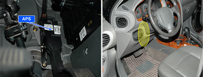

Accelerator Position Sensor is an important sensor that transmit driver’s accelerating intention to ECM for determining fuel injection quantity corresponds to the current acceleration as same mechanism with TPS.
For importance of this sensor, reliability is strongly required. thus, APS consists of APS1 from which main signal comes and APS2 which is for monitoring normal operation of APS1.
APS 1 and 2 have power supply and ground independently. the signal voltage of APS 2 is 1/2 of APS 1. When the ratio of signal of APS 1 and APS 2 is above certain value, error is recognizes and Limp home mode is activated.
When Limp home mode is activated only restricted driving is possible because engine speed is fixed at 1200RPM to protect engine from excessive power generation due to abnormal APS signal.
Item | Detecting Condition | Possible Cause | ||
DTC Strategy | ● Voltage monitoring | ● APS 1 Circuit ● APS component ● ECM component | ||
Enable Conditions | ● Ignition "ON" | |||
Threshold Value | ● When Sensor power supply 1 is below 4.7 or above 5.1V | |||
Diagnostic Time | ● 100ms | |||
Fail Safe | Fuel Cut | No | ● Limp home idle is fixed at (1200RPM) ● A/C operation stops according to Vehicle/Engine speed ● Cruise control deactivated (for Cruise control option applied vehicle) | |
EGR Off | No | |||
Fuel Limit | YES | |||
MIL | YES | |||
Sensor Power Supply 1 | Sensor Power Supply 1 related Sensors |
4.7~5.1V | APS 1, MAFS |