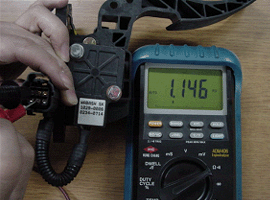
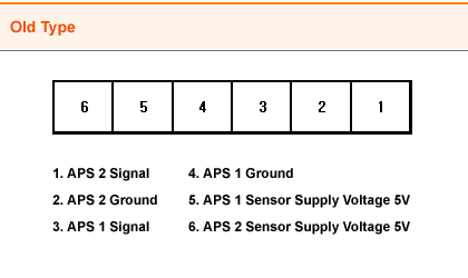
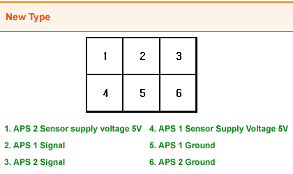
Connect the ohmmeter the probes to the APS terminal 2 and the terminal 5 and measure the resistance.
Specification
APS 1 : 1.2 ㏀ ±0.4 ㏀ at 20℃(68℉)


BASIC INSPECTION
Before performing the inspection of APS, make sure that the follwing items :
Bent or broken terminals, harness connector connection, loose wires and damage or crack.
APS NUMBERING ORDER


Connect the ohmmeter the probes to the APS terminal 2 and the terminal 5 and measure the resistance.
Specification
APS 1 : 1.2 ㏀ ±0.4 ㏀ at 20℃(68℉)

Make sure that the resistance value goes down according to the APS pedal depression.
Measure the resistance between the APS terminal 2 and terminal 5.
- If the resistance is out of specification, or if it doesn’t change smoothly, replace the APS
Do not test the APS with the analogue multimeter due to the risk of damage to the internal circuit.
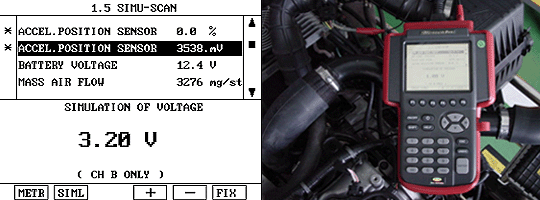
SIMU - SCAN FUNCTION IN THE SCAN TOOL (SIMV)
The SIMU-SCAN feature is capable of generating simulated voltage, frequency, and duty cyle that can be used for in-depth diagnosis while displaying current The SIMU-SCAN also allows raw and current data to be displayed simultaneouslyinformation. This test is to inspect whether or not ECM receives the output signal normally from the sensor by using a SIMU-SCAN function of the scan tool indirectly. At the same time, user is able to check the open circuit and the short circuit to ground through a scantool simulation function indirectly.
CONNECTION METHOD
① Connect to the DLC cable 16 pins to the scantool
② The probe in channel B should be connected in order to input signals for the simulation of voltage
③ Select SIMU-SCAN in Hyundai vehicle diagnosis which allows sensor outut generation and current data analysis to be performed simultaneosly
HOW TO OPERATE
Pressing this key activites sensor output Voltage simulation. The voltage generated through channel B can be set using the (+) and (-) keys in 20 ㎷ steps. If the set voltage and the applied voltage differ by less than 10%, voltage feed back control is maintained by scantool.
If the difference voltage exceeds 10%, the follwing message is displayed and no voltage output occurs. " SIMULATION SIGNAL IS DISTORETED CHECK PROBE, PRESS [ENTER] "
