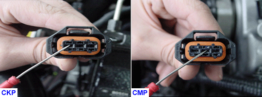
ARE THE WIRES O.K ? & ARE THE CONNECTIONS O.K ?
YES
Go to "Signal Circuit Inspection" procedure.
NO
Repair as necessary and go to " Verification of Vehicle Repair " procedure

Check for damaged harness and terminals including rubber seals :
-. contact resistance, oxidation, corrosion, bent or broken terminals
-. harness connector connection, loose wires etc.
Check for poor connection between ECM and component :
-. backed out terminal, improper mating, broken locks and poor terminal to wire connection
ARE THE WIRES O.K ? & ARE THE CONNECTIONS O.K ?
YES
Go to "Signal Circuit Inspection" procedure.
NO
Repair as necessary and go to " Verification of Vehicle Repair " procedure
DTCs listed below are stored in the scan tool
P0336/P0341/P0343/P1300
Check items with the scan tool and the multimeter
① Wiring harness inspection
② Check the CKP reference voltage
③ Check the CMP power, the reference voltage, and the waveform
Specification for checking the signal circuit
Resitance : below 1 Ω for open in the wire
Resitance : infinite for short to ground in the wire
Voltage : below 0.5V for short to power in the wire
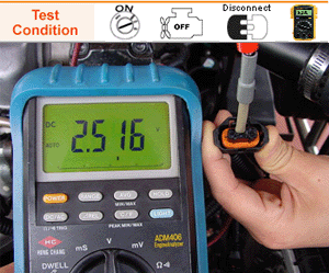
CKP reference voltage : Approx. 2.5V
Refer to the component and full circuit for connector configrations details
Disconnect the CKP and turn the ignition switch ON
Measure the voltage at the CKP terminal 2 and the CKP terminal 3 individually.
ARE THERE approx. 2.5 V ?
YES
Intermittent failure, system is O.K at this time.
Go to step 5
NO
Repair open or short in the wire between the CKP terminal 2 and the ECM terminal 19/C230-2.
Repair open or short in the wire between the CKP terminal 3 and the ECM terminal 18/C230-2.
Go to step 3

Measure the reference voltage at the ECM terminal 18/C230-2 and terminal 19/C230-2 individually.
ARE THERE approx. 2.5 V ?
YES
Recheck open or short in the wire between the CKP terminal 2 and the ECM terminal 19/C230-2.
Recheck open or short in the wire between the CKP terminal 3 and the ECM terminal 18/C230-2.
Measure the resistance between the CKP terminal 2 and the terminal 3. For more detailed information, Go to "Component Inspection" procedure.
Go to step 5
NO
Replace a known - good ECM and recheck.if the reference voltage is checked, replace the ECM.
Go to step 5
Measure the CKP resistance.
IS THERE 650 ~ 1000 Ω ?
YES
Inspect the CKP metalic parts or possible abrasion
For more detailed information, Go to "Component Inspection" procedure.
NO
Replace the CKP. Go to "Verification of Vehicle Repair" procedure.
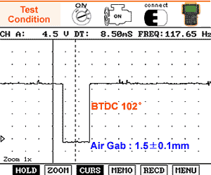
Connect the CH A probe of scan tool to the CMP sensor terminal 2 after turning the ignition switch OFF and then start the engine.
Check the CMP sensor signal waveform.
WAVEFORM ANALYSIS

This test should be inspected after depressing the HOLD mode while idling. Rectangular waveform is output even when the CMP sensor meets the dowel pin of camshaft. If the waveform pattern becomes distorted or generated no signal while cranking or idling, replace the CMP
IS THERE THE SIGNAL WAVEFORM PROPERLY DISPLAYED ?
YES
Intermittent failure, system is O.K at this time.
Check for poor connections or loose wire at the CMP sensor and the ECM.
Go to step 4
NO
Check for the interference on signal line from other component such as an alternator, injector lines.
Repair open or short in the wire between the CMP sensor terminal 2 and the ECM terminal 22/C230-2.
Go to step 4
Check the CMP sensor and the CKP sensor signal waveform again.
IS THERE THE SIGNAL WAVEFORM PROPERLY DISPLAYED ?
YES
Go to "Verification of Vehicle Repair" procedure.
NO
Replace the CMP sensor after inspecting the CMP metalic parts, possible abrasion and air cap.

WAVEFORM ANALYSIS
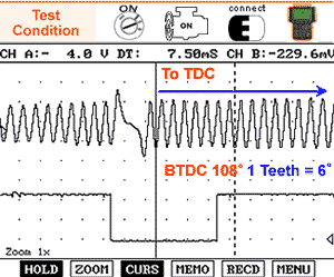
The given data is the normal waveform of the crankshaft position sensor (CKPS) and the Camshaft position sensor (CMPS). The CKP sinusoidal signal generates continuosly except 2 missing teeth. but the CMP squre waveform signal is output even when the CMP sensor meets the dowel pin of camshaft. If the waveform pattern becomes distorted or generated no signal while cranking or idling, replace the CKP or the CMP
YES
Go to "Verification of Vehicle Repair" procedure
Connect the CH A probe of scan tool to the CMP sensor terminal 2 after turning the ignition switch OFF and then start the engine
Check the CMP sensor signal waveform
WAVEFORMM ANALYSIS

This test should be inspected after depressing the HOLD mode while idling. Rectangular waveform is output even when the CMP sensor meets the dowel pin of camshaft. If the waveform pattern becomes distorted or generated no signal while cranking or idling, replace the CMP
IS THERE THE SIGNAL WAVEFORM PROPERLY DISPLAYED ?
YES
Intermittent failure, system is O.K at this time
Check for poor connections or loose wire at the CMP sensor and the ECM
Go to step 4
NO
Check for the interference on signal line from other component such as an alternator, injector lines
Repair open or short in the wire between the CMP sensor terminal 2 and the ECM terminal 22/C230-2
Go to step 4
Check the CMP sensor and the CKP sensor signal waveform again
IS THERE THE SIGNAL WAVEFORM PROPERLY DISPLAYED ?
YES
Go to "Verification of Vehicle Repair" procedure
NO
Replace the CMP sensor after inspecting the CMP metalic parts, possible abrasion and air cap

WAVEFORM ANALYSIS
The given data is the normal waveform of the crankshaft position sensor (CKPS) and the Camshaft position sensor (CMPS). The CKP sinusoidal signal generates continuosly except 2 missing teeth. but the CMP squre waveform signal is output even when the CMP sensor meets the dowel pin of camshaft. If the waveform pattern becomes distorted or generated no signal while cranking or idling, replace the CKP or the CMP
YES
Go to "Verification of Vehicle Repair" proced
DTC P1300 is detected if the following conditions are met :
① When the ECM (CKP sensor defective) is measured the signal rate between present engine speed (k) and previous engine speed (k-1). If the rate is out of standard, it is detected as an error.
② When the ECM (CMP sensor defective) is measured the limit between angular velocity of CKP signal sensing stubs and frequency multiplier of inner ECM is exceed the set value.
Therefore, this DTC P1300 is need to be analyzed the waveform of CKP sensor and CMP sensor together. in order to discriminate the defection between the CKP sensor and the CMP sensor. Through the CKP sensor and the CMP sensor signal, you can check the timing belt(camshaft and crankshaft) arrangement at secondhand. To perform this procedure, go to "Verification of Vehicle Repair" the tree on the left-hand side of the window in the first place. To check the timing belt arrangement, go to "Component Inspection" the tree on the left-hand side secondly.