Monitoring for pending DTC set ?
YES
Go to the applicable troubleshooting procedure.
NO
System OK.
After a repair, it may be necessary to check that fault is properly verified as follows.
Using a Scantool, Erase the DTC.
Review and record the current data
Check the test result is complete and turning the ignition switch off.
Monitoring for pending DTC set ?
YES
Go to the applicable troubleshooting procedure.
NO
System OK.
Erase the DTC
YES
Connect the scan tool to the data link connector(DLC) and start the engine
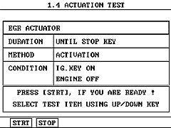
Go to the actuation test for driving the EGR sol. valve.
Pressing on the Start key
IS THE EGR SOL.VALVE ON WITH THE OPERATION NOISE ?
YES
Go to step 5
NO
Recheck the fuse and the EGR sol.valve.
Recheck the wiring harness
Recheck the fuse
Go to step 5

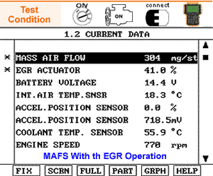
Fix the EGR actuator current data and check.
IS THERE THE MASS AIR FLOW AND THE EGR ACTUATOR PROPERLY DISPLAYED WITHIN SPECIFICATION WHILE IDLING ?
SPECIFICATION
450 ~ 510 mg/stroke (without EGR operation)
280 ~ 360 mg/stroke (with EGR operation)
EGR SOL. VALVE DUTY RATIO
95 % (closed position) ~ 20 % (opened position)
When the EGR actuator is 95% duty ratio, the EGR valve is closed by the ECM. When the EGR actuator is 20% duty ratio, the EGR valve is fully opened by the ECM
YES
The EGR system is O.K
Make sure there is no the DTC in the dignostic trouble codes menu
NO
Recheck the EGR system for checking the EGR system, Go to "Component Inspection" procedure. For checking the MAFS, Go to "DTC 0101 Verification of Vehicle Repair " procedure.
Go to step 7

MONITORING FOR PENDING DTC SET ?
YES
Go to the applicable troubleshooting procedure.
NO
System OK
Lift the vehicle up.
Connect the probe of scan tool to the VSS terminal 3 and then, test the drive.
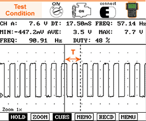
Check the VSS signal waveform when depressing the accelerator pedal fully one time.
IS THERE THE SIGNAL WAVEFORM PROPERLY DISPLAYED FROM LOW SPEED TO HIGH SPEED ?
YES
Make sure there is no the DTC in the diagnostic trouble codes menu
NO
Recheck the fuse
Recheck the wiring harness
Go to step 5

WAVEFORM ANALYSIS
This test should be inspected after depressing the HOLD mode at the vehicle speed of 120 Km/h. The time T becomes shorter and frequency increases when the engine speed is increased. If unstable waveform pattern with non-uniform frequency or no signal, replace the VSS. When the ignition switch is ON, approx. 10V is checked at the VSS terminal 3 through the ECM to the speedometer. Unless there is the voltage at the VSS terminal 3, check the continuity between the speedometer and the ECM terminal 49/C230-1 or the reference voltage at the ECM terminal 49/C230-1 directly.
MONITORING FOR PENDING DTC SET ?
YES
Go to the applicable troubleshooting procedure.
NO
System OK