
With the ignition switch in the ON or START position, voltage is applied to the ignition coil.
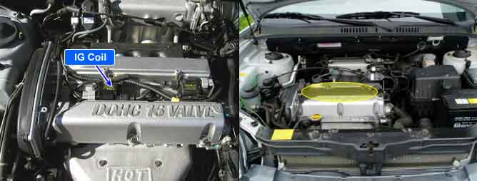
Each ignition coil consists of two coils. High tension leads go to each cylinder from the ignition coils.
The ignition coils fire two spark plugs on every power stroke (the cylinder under compression and the cylinder on the exhaust stroke). The Powertrain Control Module (PCM) provides a switching circuit to ground for energizing the primary ignition coils. The PCM uses the crankshaft position sensor and camshaft position sensor signal to time the energizing of the coil. When a primary ignition coil is energized and de-energized, the secondary coil produces a high voltage spike to the attached spark plugs.
If there is no voltage at either of 2 ignition coil group during 32 ignitions, the PCM determines that a fault exists and a DTC is stored..
Item | Detecting Condition | Possible cause |
DTC Strategy | ● Voltage of ignition coil is monitored | ● Poor connection ● Open or short in Ignition Coil circuit ● Faulty Ignition Coil #1/#2 ● Faulty PCM |
Enable Conditions | ● Engine speed < 5000rpm | |
Threshold value | ● No voltage of 1 IG coil group at the 2 IG coil group During 32 ign. | |
Diagnosis Time | ● Continuous |