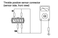
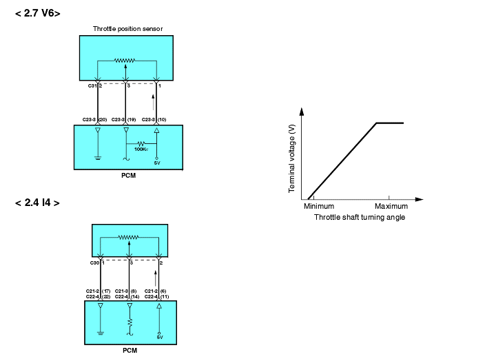
Connect a pointer type ohmmeter between terminal 1 (sensor ground) and terminal 3 (sensor output) for 2.4 I4 and between terminal 2 (sensor ground)and terminal 3 (sensor output) for 2.7 V6.


Check item | Data display | Check conditions | Throttle valve | Test specification |
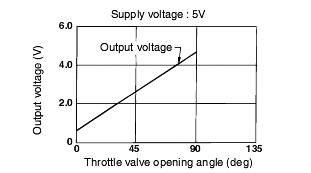
Throttle position sensor | Sensor voltage | Ignition switch : ON | At idle position | 300~900 mV (2.4 I4) 250~800 mV (2.7 V6) |
Open slowly | Increases with valve opening | |||
Open wide | 4,250~4,700 mV |
Disconnect the throttle position sensor connector.
For 2.4 I4 measure the resistance between terminal 1 (sensor ground) and terminal 2 (sensor power), for 2.7 V6 between terminal 2 (sensor ground)and terminal 1 (sensor power).
3.5 ~ 6.5 kΩ |
Connect a pointer type ohmmeter between terminal 1 (sensor ground) and terminal 3 (sensor output) for 2.4 I4 and between terminal 2 (sensor ground)and terminal 3 (sensor output) for 2.7 V6.

Operate the throttle valve slowly from the idle position to the full open position and check that the resistance changes smoothly in proportionwith the throttle valve opening angle.
If the resistance is out of specification, or fails to change smoothly, replace the throttle position sensor.
Tightening torque TP Sensor : 1.5~2.5 Nm (15~25 kg·cm, 1.1~1.8 lb·ft) |


