1.
Inspection of parts
Each part, when removed, should be carefully inspected for malfunction, deformation, damage, and other problems.
Information needed in reference to a repair service.
Information about an activity that could cause damage to the vehicle.
Information about an activity that could cause injury or damage to the driver, occupants or repairman.
ABBREVIATIONS
DOHC : Double Over Head Camshaft
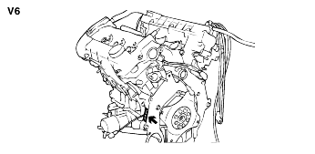
V6 : V-type 6 Cylinder
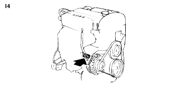
I4 : Inline 4 Cylinder
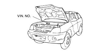
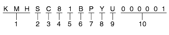
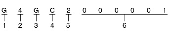
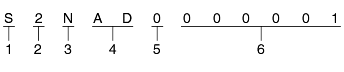
W.I.C. (World manufacturer's Identification Code)
KM8 - Hyundai Motor Company, Korea
Vehicle Line
S : SANTAFE
Model & Series
A : Standard(L)
B : Deluxe (GL)
C : Super deluxe (GLS)
D : Grand salon (GDS)
E : Super grand salon (HGDS)
Body Type
8 : Wagon
Restraint system or brake system
0 - Both side (NONE)
1 - Active Belt (Driver side + Passenger side)
2 - Passive Belt (Driver side + Passenger side)
Engine type
A : G 2.0 I4
B : G 2.4 I4
D : G 2.7 V6
V : D 2.0 TCI
Driver side
P : LHD (Left hand driver)
R : RHD (Reft hand driver)
Production year
1 - 2001 Model Year, 3 - 2003 Model yeal
2 - 2002 Model Year, 4 - 2004 Model yeal
Production plant
U - Ulsan (Korea)
Vehicle production sequence number
000001 - 999999
Engine fuel
G - Gasoline
D - Diesel
Engine range
4 - In line 4 cycle 4 cylinder
6 - V type 4 cycle 6 cylinder
Engine development order
B - V6 delta Engine
E - D - Engine
J - SIRIUS II DOHC Engine
Engine capacity
P - 1977cc
S - 2351cc
A - 2656cc (gasoline), 1991cc (diesel)
Production year
1 - 2001
2 - 2002
3 - 2003
4 - 2004
Engine production sequence number
000001 - 999999
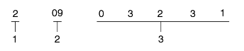
Production year
1 : 2001
2 : 2002
3 : 2003
Production month
09 - 9 (September)
12 - 12 (December)
Transmission production sequence number
000001 ~ 999999
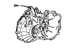
T/M Model
S : F4A51 - 2 (2.4I4, 2.7V6)
Production year
1 : 2001, 2 : 2002
3 : 2003, 4 : 2004
Final gear ratio
N : 4.018 (F4A51)
Classification of detail
AD : Damper spring type
Spare
Transmission production sequence number.
000001 ~ 999999
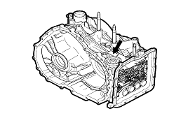
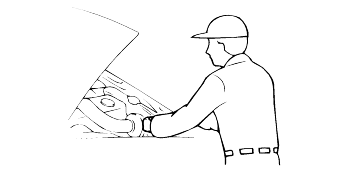
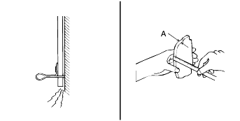
The support rod must be inserted into the hole near the edge of the hood whenever you inspect the engine compartmentto prevent the hood from falling and causing possibly injury.
Make sure that the support rod has been released prior to closing the hood. Always check to be sure the hood is firmly latched before driving thevehicle.
Block the wheels.
Place a jack under the specified jacking point.
Support the vehicle with safety stands (jack stands) Refer to page GI-10.
Start the engine when engine compartment is clean.
Inspection of parts
Each part, when removed, should be carefully inspected for malfunction, deformation, damage, and other problems.
Arrangement of parts
All disassembled parts should be carefully arranged for effective reassembly.
Be sure to separate and correctly identify the parts to be replaced from those that will be used again.
Cleaning parts for reuse
All parts to be used again should be carefully and thoroughly cleaned by the appropriate method.

If removed, the following parts should be always replaced with new ones.
Oil seals
Gaskets
O-rings
Lock washers
Cotter pins (split pins)
Plastic nuts
Depending on their location.
Sealant should be applied to gaskets.
Oil should be applied to the moving components of parts.
Specified oil or grease should be applied to the prescribed locations (oil seals, etc.) before assembly.
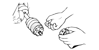
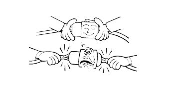
Be sure to disconnect the battery cable from the negative (-) terminal of the battery.
Never pull on the wires when disconnecting connectors.
Locking connectors will click when the connector is secure.
Handle sensors and relays carefully. Be careful not to drop them or hit them against other parts.
Basically, all measurements in this manual are taken with a tracking gauge.
When a measuring tape is used, check to be sure there is no elongation, twisting or bending.
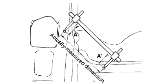
For measuring dimensions, both projected dimensions and actual-measurement dimensions are used in this manual.
These are the dimensions measured when the measurement points are projected from the vehicle's surface, and are the reference dimensionsused for body alterations.
If the length of the tracking gauge probes is adjustable, measure it by lengthening one of the two probes as long as the height of the two surfacesare different.
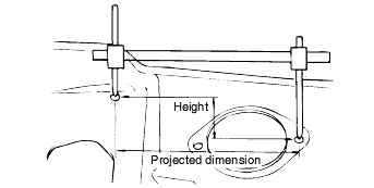
These dimensions indicate the actual linear distance between measurement points, and are used as the reference dimensions when a tracking gauge isused for measurement.
First adjust both probes to the same length (A=A') before measurement.
Check the probes and gauge itself to make sure there is no free play.
Check the terminal for tightness.
Check terminals and wires for corrosion from battery electrolyte, etc.
Check terminals and wires for open circuits.
Check wire insulation and coating for damage, cracks and degrading.
Check the conductive parts of terminals for contact with other metallic parts (vehicle body and other parts).
Check grounded parts to verify that there is complete continuity between their attaching bolt(s) and the vehicle's body.
Check for incorrect wiring.
Check that the wiring is clamped firmly to prevent contact with sharp corners of the vehicle body, etc. or hot parts (exhaust manifold, etc.)
Check that the wiring is clamped firmly to provide enough clearance from the fan pulley, fan belt and other rotating or moving parts.
Check that the wiring has a little space so that it can vibrate between the fixed and moving parts such as the vehicle body and the engine.
Prior to servicing the electrical system, be sure to turn off the ignition switch and disconnect the battery ground cable.
In the course of MFI or ELC system diagnosis, when the battery cable is removed, any diagnostic trouble code retained by the computer will be cleared. Therefore, if necessary, read the diagnosticcodes before removing the battery cable.
Attach the wiring harnesses with clamps so that there is no slack. However, for any harness which passes the engine or other vibrating parts of the vehicle, allow some slack within a range that does not allow the engine vibrations to cause the harness to come into contact with any of the surroundingparts, and then secure the harness by using a clamp.
If any section of a wiring harness interferes with the edge of a part, or a corner, wrap the section of the harness with tape or somethingsimilar in order to protect it from damage.
When installing any parts, be careful not to pinch or damage any of the wiring harnesses.
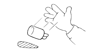
Never throw relays, sensors or electrical parts, or expose them to strong shock.
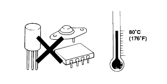
The electronic parts used in the computer, relays, etc. are readily damaged by heat. If there is a need for service operations that may cause the temperature to exceed 80°C (176°F ), remove the electronic partsbeforehand.
Loose connectors cause problems. Make sure that the connectors are always securely fastened.
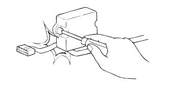
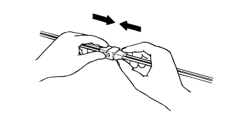
When disconnecting a connector, be sure to grip only the connector, not the wires.
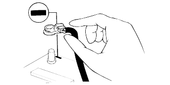
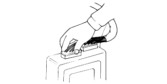
Disconnect connectors which have catches by pressing in the direction of the arrows shown the illustration.
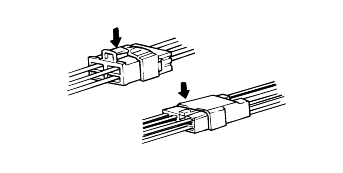
Connect connectors which have catches by inserting the connectors until they make a clicking sound.
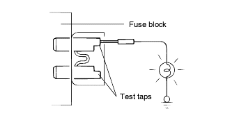
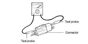
When, using a circuit tester, to check continuity or voltage on connector terminals, insert the test probe into the harness side. If the connector is a sealed connector, insert the test probe through the hole in the rubber cap until it contacts the terminal, being careful not to damage the insulationof the wires.
To avoid overloading the wiring, take the electrical current load of the optional equipment into consideration, and determine the appropriatewire size.
Norminal size | SAE gauge No. | Permissible current | |
In engine compartment | Other areas | ||
0.3 mm² | AWG 22 | - | 5A |
0.5 mm² | AWG20 | 7A | 13A |
0.85 mm² | AWG18 | 9A | 17A |
1.25 mm² | AWG16 | 12A | 22A |
2.0 mm² | AWG14 | 16A | 30A |
3.0 mm² | AWG12 | 21A | 40A |
5.0 mm² | AWG10 | 31A | 54A |
If a large amount of unburned gasoline flows into the converter, it may overheat and create a fire hazard. To prevent this,observe the following precautions and explain them to your customer.
Use only unleaded gasoline.
Do not run the engine while the car is at rest for a long time. Avoid running the engine at fast idle speed for more than 10 minutes and atidle speed for more than 20 minutes.
Avoid spark- jump tests. Do spark- jumps only when absolutely necessary. Perform this test as rapidly as possible and, while testing, neverrace the engine.
Do not measure engine compression for an extended time. Engine compression tests must be made as rapidly as possible.
Do not run the engine when the fuel tank is nearly empty. This may cause the engine to misfire and create an extra load on the converter.
Avoid coasting with the ignition turned off and during prolonged braking.
Do not dispose of a used catalytic converter together with parts contaminated with gasoline or oil.
Work must be started approx. 30 seconds or longer after the ignition switch is turned to the LOCK position and the negative (-) battery cable is disconnected. (The airbag system is equipped with a back-up power source. If work is started within 30 seconds after disconnecting the negative (-) terminal cable of the battery, the airbag may be operative.) When the negative (-) terminal cable is disconnected from the battery, the clock and audio systems memories will be erased. Before starting work, record the setting of the audio memory system. When work is finished, reset the audio system as beforeand adjust the clock.
Malfunction symptoms of the airbag system are difficult to confirm, so diagnostic codes become the most important source of information when troubleshooting. When troubleshooting the airbag system, always read the diagnostic codes beforedisconnecting the battery.
Never use airbag parts from another vehicle. When replacing parts, replace them with new parts.
Never attempt to disassemble and repair the airbag modules, SRSCM, clock spring and airbag wiring harness in order to reuse it.
If the SRSCM or airbag module has been dropped, or if there are cracks, dents or other defects in the case, bracket or connector, replacethem with new ones.
After work on the airbag system is completed, re-set the SRS SRI.
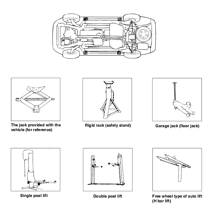
Never use a jack beneath the lateral rod or rear suspension assembly.
In order to prevent scratching the sub frame, place a piece of cloth on the jack's contact surface (to prevent corrosion caused by damageto the coating).
Never support vehicle with only a jack. Always use safety stands.
Do not attempt to raise one entire side of the vehicle by placing a jack midway between the front and rear wheels. To do so could result inpermanent damage to the body.
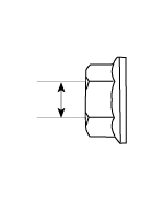
BOLT (Nominal diameter) | NUT (Nominal diameter) | ||
 | 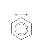 |
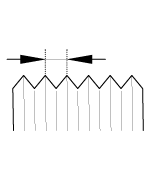
BOLT/NUT Thin screw | Torque Nm (kg.m, Ib-ft) | |||
Nominal diameter. (mm) | Pitch [mm (in.) ] | 4T | 8T | 10T |
 |  |  | 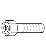 | |
M5 | 0.8 (0.031) | 2.0 ~ 3.0 (0.2 ~ 0.3, 1.4 ~ 2.2) | 4.9 ~ 6.9 (0.5 ~ 0.7, 3.6 ~ 5.1) | 7.8 ~ 10.8 (0.8 ~ 1.1, 5.8 ~ 8.0) |
M6 | 1 (0.039) | 2.9 ~ 4.9 (0.3 ~ 0.5, 2.2 ~ 3.6) | 8.8 ~ 12.7 (0.9 ~ 1.3, 6.5 ~ 9.4) | 13.7 ~ 18.6 (1.4 ~ 1.9, 10.1 ~ 13.7) |
M8 | 1.25 (0.049) | 8.8 ~ 11.8 (0.9 ~ 1.2, 6.5 ~ 8.7) | 22.6 ~ 30.4 (2.3 ~ 3.1, 16.6 ~ 22.4) | 33.3 ~ 44.1 (3.4 ~ 4.5, 24.6 ~ 32.5) |
M10 | 1.5 (0.059) | 16.7 ~ 22.6 (1.7 ~ 2.3, 12.3 ~ 16.6) | 45.1 ~ 60.8 (4.6 ~ 6.2, 33.3 ~ 44.8) | 65.7 ~ 88.3 (6.7 ~ 9.0, 48.5 ~ 65.1) |
M12 | 1.75 (0.068) | 29.4 ~ 39.2 (3.0 ~ 4.0, 21.7 ~ 28.9) | 78.5 ~ 105.9 (8.0 ~ 10.8, 57.9 ~ 78.1) | 114.7 ~ 154.9 (11.7 ~ 15.8, 84.6 ~ 114.3) |
M14 | 2 (0.078) | 47.1 ~ 63.7 (4.8 ~ 6.5, 34.7 ~ 47.0) | 125.5 ~ 169.7 (12.8 ~ 17.3, 92.6 ~ 125.1) | 183.4 ~ 249.1 (18.7 ~ 25.4, 135.3 ~ 183.7) |
M16 | 2 (0.078) | 73.5 ~ 100.0 (7.5 ~ 10.2, 54.2 ~ 73.8) | 197.1 ~ 266.7 (20.1 ~ 27.2, 145.4 ~ 196.7) | 288.3 ~ 390.3 (29.4 ~ 39.8, 212.7 ~ 287.9) |
M20 | 2.5 (0.098) | 144.2 ~ 195.2 (14.7 ~ 19.9, 106.3 ~ 143.9) | 396.2 ~ 535.4 (40.4 ~ 54.6, 292.2 ~ 394.9) | 565.8 ~ 764.9 (57.7 ~ 78.0, 417.3 ~ 564.2) |
M24 | 3 (0.118) | 249.1 ~ 337.3 (25.4 ~ 34.4, 183.7 ~ 248.8) | 687.4 ~ 929.7 (70.1 ~ 94.8, 507.0 ~ 685.7) | 975.8 ~ 1320.0 (99.5 ~ 134.6, 719.7 ~ 973.6) |
M30 | 3.5 (0.137) | 499.2 ~ 674.7 (50.9 ~ 68.8, 368.2 ~ 497.6) | 1372.9 ~ 1858.4 (140.0 ~ 189.5, 1012.6 ~ 1370.7) | 1956.4 ~ 2647.8 (199.5 ~ 270.0, 1443.0 ~ 1952.9) |
BOLT/NUT Thin screw | Torque Nm (kg.m, Ib-ft) | |||
Nominal diameter. (mm) | Pitch [mm (in.) ] | 4T | 8T | 10T |
| | | | |
M5 | 0.5 (0.019) | 2.0 ~ 3.0 (0.2 ~ 0.3, 1.4 ~ 2.2) | 5.9 ~ 8.8 (0.6 ~ 0.9, 4.3 ~ 6.5) | 8.8 ~ 12.7 (0.9 ~ 1.3, 6.5 ~ 9.4) |
M6 | 0.75 (0.029) | 3.9 ~ 4.9 (0.4 ~ 0.5, 2.9 ~ 3.6) | 9.8 ~ 13.7 (1.0 ~ 1.4, 7.2 ~ 10.1) | 14.7 ~ 20.6 (1.5 ~ 2.1, 10.8 ~ 15.2) |
M8 | 1 (0.039) | 8.8 ~ 11.8 (0.9 ~ 1.2, 6.5 ~ 8.7) | 24.5 ~ 32.4 (2.5 ~ 3.3, 18.1 ~ 23.9) | 35.3 ~ 48.1 (3.6 ~ 4.9, 26.0 ~ 35.4) |
M10 | 1.25 (0.049) | 17.7 ~ 23.5 (1.8 ~ 2.4, 13.0 ~ 17.4) | 47.1 ~ 63.7 (4.8 ~ 6.5, 34.7 ~ 47.0) | 69.6 ~ 94.1 (7.1 ~ 9.6, 51.4 ~ 69.4) |
M12 | 1.25 (0.049) | 32.4 ~ 44.1 (3.3 ~ 4.5, 23.9 ~ 32.5) | 86.3 ~ 117.7 (8.8 ~ 12.0, 63.7 ~ 86.8) | 127.5 ~ 172.6 (13.0 ~ 17.6, 94.0 ~ 127.3) |
M14 | 1.5 (0.059) | 51.0 ~ 69.6 (5.2 ~ 7.1, 37.6 ~ 51.4) | 136.3 ~ 185.3 (13.9 ~ 18.9, 100.5 ~ 136.7) | 201.0 ~ 271.6 (20.5 ~ 27.7, 148.3 ~ 200.4) |
M16 | 1.5 (0.059) | 79.4 ~ 107.9 (8.1 ~ 11.0, 58.6 ~ 79.6) | 211.8 ~ 286.4 (21.6 ~ 29.2, 156.2 ~ 211.2) | 311.8 ~ 421.7 (31.8 ~ 43.0, 230.0 ~ 311.0) |
M20 | 1.5 (0.059) | 163.8 ~ 221.6 (16.7 ~ 22.6, 120.8 ~ 163.5) | 448.2 ~ 607.0 (45.7 ~ 61.9, 330.5 ~ 447.7) | 639.4 ~ 864.9 (65.2 ~ 88.2, 471.6 ~ 638.0) |
M24 | 2 (0.078) | 276.5 ~ 373.6 (28.2 ~ 38.1, 204.0 ~ 275.6) | 759.0 ~ 1026.8 (77.4 ~ 104.7, 559.8 ~ 757.3) | 1080.7 ~ 1462.2 (110.2 ~ 149.1, 797.1 ~ 1078.4) |
M30 | 2 (0.078) | 562.9 ~ 762.0 (57.4 ~ 77.7, 415.2 ~ 562.0) | 1553.4 ~ 2102.5 (158.4 ~ 214.4, 1145.7 ~ 1550.8) | 2210.4 ~ 2991.0 (225.4 ~ 305.0, 1630.3 ~ 2206.1) |
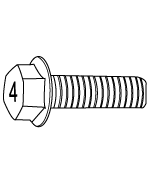
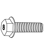
Flange BOLT (Nominal diameter) | Flange NUT (Nominal diameter) | ||
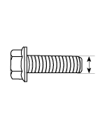 |  |
Flange BOLT/NUT Normal screw | Torque Nm (kg.m, Ib-ft) | |||
Nominal diameter. (mm) | Pitch [mm (in.) ] | 4T | 8T | 10T |
|  |  |  | |
M5 | 0.8 (0.031) | 2.0 ~ 2.9 (0.2 ~ 0.3, 1.4 ~ 2.2) | 5.9 ~ 7.8 (0.6 ~ 0.8, 4.3 ~ 5.8) | 8.8 ~ 11.8 (0.9 ~ 1.2, 6.5 ~ 8.7) |
M6 | 1 (0.039) | 3.9 ~ 4.9 (0.4 ~ 0.5, 2.9 ~ 3.6) | 9.8 ~ 13.7 (1.0 ~ 1.4, 7.2 ~ 10.1) | 14.7 ~ 19.6 (1.5 ~ 2.0, 10.8 ~ 14.5) |
M8 | 1.25 (0.049) | 8.8 ~ 11.8 (0.9 ~ 1.2, 6.5 ~ 8.7) | 24.5 ~ 32.4 (2.5 ~ 3.3, 18.1 ~ 23.9) | 35.3 ~ 48.1 (3.6 ~ 4.9, 26.0 ~ 35.4) |
M10 | 1.5 (0.059) | 17.7 ~ 24.5 (1.8 ~ 2.5, 13.0 ~ 18.1) | 48.1 ~ 65.7 (4.9 ~ 6.7, 35.4 ~ 48.5) | 70.6 ~ 96.1 (7.2 ~ 9.8, 52.1 ~ 70.9) |
M12 | 1.75 (0.068) | 31.4 ~ 43.1 (3.2 ~ 4.4, 23.1 ~ 31.8) | 84.3 ~ 113.8 (8.6 ~ 11.6, 62.2 ~ 83.9) | 123.6 ~ 167.7 (12.6 ~ 17.1, 91.1 ~ 123.7) |
M14 | 2 (0.078) | 51.0 ~ 68.6 (5.2 ~ 7.0, 37.6 ~ 50.6) | 135.3 ~ 182.4 (13.8 ~ 18.6, 99.8 ~ 134.5) | 198.1 ~ 268.7 (20.2 ~ 27.4, 146.1 ~ 198.2) |
M16 | 2 (0.078) | 79.4 ~ 107.9 (8.1 ~ 11.0, 58.6 ~ 79.6) | 212.8 ~ 288.3 (21.7 ~ 29.4, 157.0 ~ 212.7) | 311.8 ~ 421.7 (31.8 ~ 43.0, 230.0 ~ 311.0) |
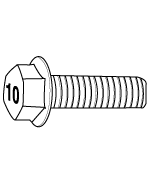
Flange BOLT/NUT Thin screw | Torque Nm (kg.m, Ib-ft) | |||
Nominal diameter. (mm) | Pitch [mm (in.) ] | 4T | 8T | 10T |
| | | | |
M5 | 0.5 (0.019) | 2.9 ~ 2.9 (0.3 ~ 0.3, 2.2 ~ 2.2) | 6.9 ~ 8.8 (0.7 ~ 0.9, 5.1 ~ 6.5) | 9.8 ~ 13.7 (1.0 ~ 1.4, 7.2 ~ 10.1) |
M6 | 0.75 (0.029) | 3.9 ~ 5.9 (0.4 ~ 0.6, 2.9 ~ 4.3) | 10.8 ~ 14.7 (1.1 ~ 1.5, 8.0 ~ 10.8) | 16.7 ~ 21.6 (1.7 ~ 2.2, 12.3 ~ 15.9) |
M8 | 1 (0.039) | 9.8 ~ 12.7 (1.0 ~ 1.3, 7.2 ~ 9.4) | 26.5 ~ 35.3 (2.7 ~ 3.6, 19.5 ~ 26.0) | 38.2 ~ 52.0 (3.9 ~ 5.3, 28.2 ~ 38.3) |
M10 | 1.25 (0.049) | 19.6 ~ 25.5 (2.0 ~ 2.6, 14.5 ~ 18.8) | 51.0 ~ 68.6 (5.2 ~ 7.0, 37.6 ~ 50.6) | 75.5 ~ 102.0 (7.7 ~ 10.4, 55.7 ~ 75.2) |
M12 | 1.25 (0.049) | 35.3 ~ 48.1 (3.6 ~ 4.9, 26.0 ~ 35.4) | 94.1 ~ 126.5 (9.6 ~ 12.9, 69.4 ~ 93.3) | 138.3 ~ 186.3 (14.1 ~ 19.0, 102.0 ~ 137.4) |
M14 | 1.5 (0.059) | 55.9 ~ 75.5 (5.7 ~ 7.7, 41.2 ~ 55.7) | 148.1 ~ 200.1 (15.1 ~ 20.4, 109.2 ~ 147.6) | 216.7 ~ 293.2 (22.1 ~ 29.9, 159.8 ~ 216.3) |
M16 | 1.5 (0.059) | 86.3 ~ 116.7 (8.8 ~ 11.9, 63.7 ~ 86.1) | 229.5 ~ 309.9 (23.4 ~ 31.6, 169.3 ~ 228.6) | 336.4 ~ 455.0 (34.3 ~ 46.4, 248.1 ~ 335.6) |
The torques shown in the table are standard values under the following conditions.
Nuts and bolts are made of galvanized steel bar.
Galvanized plain steel washers are inserted.
All nuts, bolts and plain washers are dry.
The torques shown in the table are not applicable.
When spring washers, toothed washers and the like are inserted.
If plastic parts are fastened.
If self-tapping screws or self-locking nuts are used.
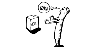
If threads and surfaces are coated with oil.
Parts | Specifications | Remarks |
Engine oil | API Classification SG Above API Classification SH Above API Classification CE Above (Diesel) | For further details, refer to SAE viscosity number |
Manual transaxle | API classification GL-4 | SAE grade number: SAE 75W/90 |
Automatic transaxle | DIAMOND ATF SP-3, SK ATF SP-3 | |
Brake | DOT 3 or DOT 4 | |
Cooling system | High quality ethylene glycol | Concentration level 50% (normal) |
Concentration level 40% (tropical) | ||
Power steering | PSF-3 | |
Transaxle linkage, parking brake cable mechanism, hood lock and hook, door latch, seat adjuster, tailgate latch,door hinges, tailgate hinges | Multipurpose grease NLGI grade #2 |
Always use GL - 4 Classification for the manual transaxle (Do not use GL - 5 Classification)
Always use Genuine Hyundai parts and recommended fluid.
Using any other type of parts and fluid can cause serious damage of the vehicle.
Description | Capacities | |||
2.0 I4 / 2.4 I4 | 2.7 V6 | Diesel | ||
Oil pan | 4.0 (4.21, 3.52) | 4.2 (4.44, 3.69) | 5.4 (5.71, 4.75) | |
Engine oil | Oil filter | 0.3 (0.32, 0.26) | 0.3 (0.32, 0.26) | 0.5 (0.53, 0.44) |
Total | 4.3 (4.53, 3.78) | 4.5 (4.76, 3.95) | 5.9 (6.24, 5.19) | |
Cooling system | 7.0 (7.35, 6.19) | 7.0 (7.35, 6.19) | 8.7 (9.19, 7.66) | |
Manual transaxle | 2.1 (2.20, 1.80) | 2.1 (2.20, 1.80) | 2.1 (2.20, 1.80) | |
Automatic transaxle | 7.8 (8.2, 6.90) | 8.5 (8.94, 7.52) | 8.5 (8.94, 7.52) | |
Power steering | 1.0 (1.05, 0.88) | 1.0 (1.05, 0.88) | 1.0 (1.05, 0.88) | |
liter (U.S. qts., Imp. qts.)
If the engine is cold, run the engine until it reaches normal operating temperature.
Turn off the engine.
Remove the oil filler cap and drain plug. Drain the engine oil.
Tighten the drain plug to the specified torque.
Tightening torque Oil pan drain plug : |
35 - 45 Nm (350 - 450 kg.cm, 25 - 33 lb.ft) |
Whenever tightening the oil drain plug, use a new drain plug gasket.
Fill new engine oil through the oil filler cap opening.
Do not overfill, this will cause oil aeration and loss of oil pressure.
Install the oil filler cap.
Start and run the engine.
Turn off the engine and then check the oil level. Add oil if necessary.
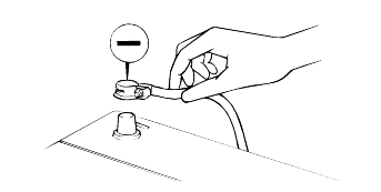
Use a filter wrench to remove the oil filter.
Before installing a new oil filter on the engine, apply clean engine oil to the surface of the rubber gasket.
Tighten the oil filter to the specified torque.
Tightening torque |
Oil filter : 12 - 16 Nm (120 - 160 kg.cm, 9 - 12 lb.ft) |
Start and run the engine and check for engine oil leaks.
After turning off the engine, check the oil level and add oil as necessary.

Disconnect the clip holding air cleaner filter cover.
Remove the air filter cover.
The air filter cover should be removed carefully because intake hose includes the air-flow sensor.

Remove the air cleaner filter.
Install a new air cleaner filter and replace the air cleaner filter cover.
The belt tension is automatically adjusted by the auto-tensioner.
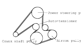
Refer to the EM and EMA-Sections.
The engine cooling system is provided with a mixture of 50% ethylene glycol anti-freeze and 50% water (For the vehicles of tropical area, the engine cooling system is provided with a mixture of 40% ethylene glycol anti-freezeand 60% water at the time of manufacture.)
Since the cylinder head and water pump body are made of aluminum alloy casting, be sure to use a 30 to 60% ethylene glycol antifreeze coolant toassure corrosion protection and freezing prevention.
If the concentration of the antifreeze is below 30%, the anticorrosion property will be adversely affected. In addition, if the concentration is above 60%, both the antifreeze and engine cooling properties will decrease, adversely affecting the engine. For these reasons,be sure to maintain the concentration level within the specified range.

Run the engine until the coolant is fully mixed. Drain some coolant (antifreeze), and then measure the temperature and specific gravity of the coolant. Determine its concentration and safe working temperature. If the coolant is short of antifreeze, add antifreeze to a concentration of 50%.(Tropical Areas : 40%)

Set the temperature control lever to the hot position.
Remove the radiator cap.
Remove the cap slowly. The system is pressurized and the coolant may be hot. Do not open the cap when the engine is hot.

Loosen the drain plug to drain the coolant.
Drain the coolant from the reserve tank.
After draining the coolant, tighten the drain plug securely.
Fill the radiator with the coolant up to its filler neck.
Fill the reserve tank with the coolant.
Warm up the engine until the thermostat opens, remove the radiator cap and check the coolant level.
When the radiator is filled up to its filler neck, install the radiator cap securely.
Fill the reserve tank with coolant up to the "FULL" line.
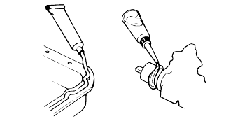
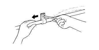
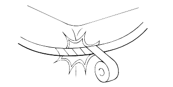
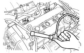
When disconnecting an ignition cable, be sure to hold the cable cap. If the cable is disconnected by pulling on the cablealone, an open circuit might result.
Tank, Lines And Connections
Check for damage or leakage in the fuel lines and connections.
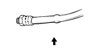
Inspect the surface of fuel hoses for heat and mechanical damage. Hard and brittle rubber, cracking, tears, cuts, abrasions and excessive swellingindicate deterioration of the rubber.
If the fabric casing of the rubber hose is damaged by cracks and abrasions in the fuel system, the hoses should be changed.
With the vehicle parked at a level place, remove the filler plug and make sure that the oil level is the same level as the plug hole.
Check that the transaxle oil is not dirty.
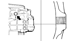
With the vehicle parked at a level place, remove the magnetic plug and drain transaxle oil.
Replace the washer with a new one and reinstall the plug.
Fill with transaxle oil (through the filler plug part) until the oil level is the same level as the plug hole.
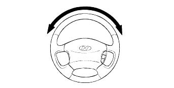
Check the steering wheel freeplay.
Maximum steering wheel freeplay : 30 mm (1.181 in.) |
Check the steering linkage for looseness and damage.
Tie rod ends must not have excessive play. Dust seals and boots must not be damaged. Boot clamps must not be loose. |
Park the vehicle on a level surface, start the engine, and then turn the steering wheel several times to raise the temperature of the fluidto approximately 50°C (122°F).
With the engine idling, turn the wheel all the way to the left and right several times. Check the fluid in the oil reservoir for foaming, and its level. Replenish the fluid in the oil reservoir through the oil filterif necessary.
Check the hose connections for fluid leaks.
The power steering hoses should be replaced if there is severe surface cracking, pulling, scuffing or worn steps. Deterioration of the hosescould cause premature failure.
These components, which are permanently lubricated at the factory, do not require lubrication. Damaged seals and boots should be replaced toprevent leakage or contamination of the grease.
Inspect the dust covers and boots for proper sealing, leakage and damage. Replace them if defective.
Check all brake lines and hoses for damage, wear, cracks, corrosion, leaks, bends and twists.
Check all clamps for tightness.
Check that the lines are clear of sharp edges, moving parts and the exhaust system.
If a squealing or scraping noise occurs from the brake during driving, check if the pad wear indicator is contacting thedisc. If it is, the brake pads should be replaced.
The pads for the right and left wheels should be replaced at the same time. Never split or intermix brake pad sets. Allpads must be replaced as a complete set.
Thickness of pad lining [Limit] : 2.0 mm (0.079 in.) |
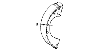
Remove the brake drum and check the thickness of the brake shoe lining for wear. Check the automatic brake adjusting system by hand to see that it operates smoothly, and gears are in proper mesh with each other. To assure smoth function, apply a very thin coat of grease to the friction surfaceof the adjuster and link shaft.
Inspect the wheel cylinder boots for fluid leaks. Visually check the boots for cuts, tears or heat cracks. (A small amount of fluid on theboot may not be a leak but preservative fluid used at assembly.)
Checking the brake shoes for wear.
Thickness of lining [Limit] : 0.8 mm (0.031 in.) |
Check the level of the brake fluid in the reserve tank of the master cylinder.
The level should be between the "MAX" and "MIN" mark.
If the level is lower than the "MIN" mark, add new brake fluid up to the "MAX" mark.
Refer to BR-Section for air-bleeding procedures.
With a vehicle equipped with ABS(Anti-lock Brake System), refer to BR-section.
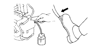
Connect a vinyl tube to the bleeder screw of each wheel cylinder. Put the other end of the vinyl tube in a vessel to receive the brake fluid.
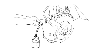
Depress the brake pedal a few times. Then loosen the bleeder screw(with the brake pedal still depressed), and tighten it after the brake fluid stopsflowing.
Repeat the above operation until there are no air bubbles in the brake fluid.
Repeat these steps for the other cylinders.
Add new brake fluid up to the "MAX" level in the reserve tank.
Brake fluid : DOT 3 or DOT4 |
Tire size | Front | Rear | |
2WD | 215/70R15 | 30 psi | 30 psi |
4WD | 225/70R16 | 30 psi | 30 psi |
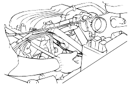
Check oil, fluid, fuel, water and exhaust gas leaks.
Check free play of clutch pedal and brake pedal.
Check operation of brake booster.
Check the operation of service brake and parking brake systems.
Check the stroke of parking brake lever.
Check the driveability of engine.
Check the condition of instruments, gauges, indicators, exterior lamps, heater and ventilators.
Check the abnormal noises from each part.
Aluminum wheels require special attention. If salt or chemicals adhere to the wheels, they need to be rinsed off as soon as possible. After cleaning the wheels, apply a coating of wax to them to prevent corrosion.
When cleaning the vehicle with steam, do not direct steam onto the aluminum wheels.
● Clean the hub surface. ● After tightening the wheel nuts by hand, tighten them according to specifications. ● Do not use an impact wrench or stand on the wrench with your foot to tighten the wheel nuts. ● Do not apply oil to the threaded portions. |
Use tire chains only on the front wheels. Do not use tire chains on rear wheels.
When using snow tires, use them on all four wheels for added maneuverability and safety.
This vehicle is full time 4WD. so, take a proper measure befor I/M testing.
I/M Testing means that Inspection and Maintenance test.
