IS THE IATS SIGNAL CHANGED PROPERLY ACCORDING TO THE SIMULATION OF VOLTAGE ?
YES
Go to step 8
NO
Recheck open or short in the wire between the FTS terminal 2 and ECM terminal 1/C230-2.
Go to step 6

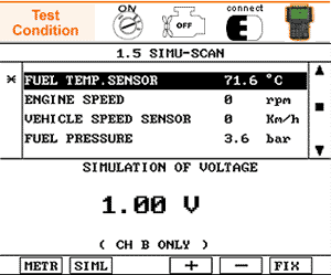
Connect the scan tool to the data link connector(DLC) and turn the ignition switch ON
Go to SIMU-SCAN
Fix the intake air temperature current data for the voltage simulation
For SIMU-SCAN function information, Go to "Component Inspection" procedure
Apply the simulation voltage to the FTS terminal 2.
IS THE IATS SIGNAL CHANGED PROPERLY ACCORDING TO THE SIMULATION OF VOLTAGE ?
YES
Go to step 8
NO
Recheck open or short in the wire between the FTS terminal 2 and ECM terminal 1/C230-2.
Go to step 6

Apply the simulation voltage to the ECM terminal 1/230-2 directly.
IS THE IATS SIGNAL CHANGED PROPERLY ACCORDING TO THE SIMULATION OF VOLTAGE ?
YES
Go to step 8
NO
Replace a known - good ECM and if normal FTS readings are indicated, replace the ECM
FUEL TEMPERAURE SENSOR DATA
Temperature [℃] | Resistance [kΩ] | Tolerance (%) |
-40 (-40℉) | 48.14 | within ± 2% |
-20 (-4℉) | 15.48±1.35 | |
0 (32℉) | 5.79 | |
20 (68℉) | 2.45±0.14 | |
40 (104℉) | 1.148 | |
60 (140℉) | 0.5865 | |
80 (176℉) | 0.3222 | |
100 (212℉) | 0.1884 | |
110 (230℉) | 0.1471±0.002 | |
120 (248℉) | 0.1163 |
There is a signal voltage or a output value difference due to the contact resistnace or any other reasons between the probe and the sensor terminal.
Perform the test drive
MONITORING FOR PENDING DTC SET ?
YES
Go to the applicable troubleshooting procedure.
NO
System OK