YES
Go to "Inspection of sensor power line"
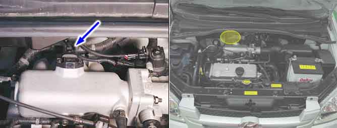
The Manifold Absolute Pressure(MAP) sensor measures the change of pressure in the intake manifold. The pressure of intake manifold is changed as variable engine running condition and converted into voltage and then it is monitored by the ECM.
The ECM sets DTC P0106 if the ECM detects signal voltage out of its properly operating range.
Item | Detecting Condition | Possible cause |
Monitoring Strategy | ● Poor connections ● Bad MAP sensor ● Bad ECM ● Bad TPS ● Dirty air cleaner ● Air leak in intake system ● Contaminated, deterriorated or damaged MAP sensor | |
Threshold value | ||
Enable Conditions | ||
Diagnostic Time | ||
MIL on condition | ● 2 driving cycle |
If any codes relating to TPS are present,do all repairs associated with before proceeding this troubleshooting procedure.
Specification
idle : 0.3~0.9V
full : 4.0~4.4V
Specification
idle : 0.3~0.9V
full : 4.0~4.4V
Is voltege signal increase?
YES
Go to "Inspection of sensor power line"
NO
Temporarily install a known good TPS and check for proper operation.
If problem is corrected, replace TPS.
Repair as necessary and go to "Verification of Vehicle Repair"
Turn ignition switch to OFF and disconnect MAP connector.
Turn ignition switch to ON
Measure voltage of TPS reference voltage(5V) circuit between MAP harness connector and ECM harness connector.
Probe(+) : MAP harness connector NO2.
Probe(-) : Chassis ground.
Specification: Approximately 5V
Is voltage within Specification?
YES
Go to "Inspection of short between MAP signal line and ground line
NO
Open circuit or short circuit to chassis ground between MAP harness connector and reference voltage.
Open circuit or short circuit to chassis ground between MAP harness connector and ECM connector.
Repair as necessary and go to "Verification of Vehicle Repair"
1.In case,when MAP connector is disconnected,the voltage of MAP terminal 2 is 0 V.
Possible cause: Open or short between terminal 33 of ECM and Terminal 2 of MAP
Checking open circuit of MAP signal line is to find whether there is open or short circuit in MAP harness.
Turn ignition switch to OFF and disconnect MAP sensor connector.
Turn ignition switch to ON
Measure voltage of MAP signal circuit between MAP harness connector and ECM harness connector.
Probe(+) : MAP harness connector NO1.
Probe(-) : Chassis ground.
Specification: Approximately 5V
Is voltage within Specification?
YES
Go to "Ispection of MAP ground line open circuit"
NO
Open circuit or short circuit to chassis ground between MAP harness connector and signal circuit.
Open circuit between MAP harness connector and ECM harness connector.
Repair as necessary and go to "Verification of Vehicle Repair"
1.In case,when MAP sensor connector is disconnected, the voltage of terminal 1 is 0V.
▶Possible cause : Open or short between terminal 37 of ECM and terminal 1 of MAP sensor.
The inspection of ground line is to find whether there is any open or short in harness.
Turn ignition switch to OFF and disconnect MAP connector.
Turn ignition switch to ON
Measure voltage or resistance of MAP ground circuit between MAP harness connector and ECM harness connector.
Probe(+) : MAP harness connector NO4.
Probe(-) : Chassis ground
Specification: below 0.5V, below 1Ω
Is voltage and resistance within Specification?
YES
Go to "Air intake system inspection"
NO
Open circuit between MAP harness connector and ECM harness connector.
Repair as necessary and go to "Verification of Vehicle Repair"
1.In case,when MAP sensor connector is disconnected, the resistence of terminal 4 is infinite.
▶Possible cause : Open or short between terminal 36 of ECM and terminal 4 of MAP sensor.
When checking TPS waveform,it is strongly recommended to examine waveform with MAP sensor waveform.
Peride ① is the voltage of MAP in idling and 0.8~1.2 V,and there must be a little fluctuation in waveform.
In case there is no fluctuation
Possible cause : Deteriorated MAP sensor or some foreign material in MAP sensor.
The voltage in Periode ② is 0.3~1.0V in average.
Periode ③ is in W.O.T and the voltage there is 4.3 V,and MAP sensor voltage is about 4.3 V.
In case there is no symptom and wrong data but DTC is shown
In case there is no symptom and wrong data but DTC is shown
The problem may be intermittent so slightly shake the connector and harness vertically and horizontally to check if there is any data changes
If the data changes normally, the problem was intermittent so erase DTC and verify the same DTC reoccure.
Go to "Terminal and Connector inspection" procedure.
In case there is symptom and wrong data with DTC
Check open,short or connector’s connection for MAP.
Check the deterioration of MAP performance.
Go to "Visual inspection" procedure.
When checking TPS waveform,it is strongly recommended to examine waveform with MAP sensor waveform.
Peride ① is the voltage of MAP in idling and 0.8~1.2 V,and there must be a little fluctuation in waveform.
In case there is no fluctuation
Possible cause : Deteriorated MAP sensor or some foreign material in MAP sensor.
The voltage in Periode ② is 0.3~1.0V in average.
Periode ③ is in W.O.T and the voltage there is 4.3 V,and MAP sensor voltage is about 4.3 V.
