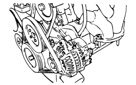
Lift the vehicle by using of jack.
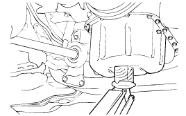
Lift the vehicle by using of jack.

Remove the engine support bracket. (14 mm bolt and 2 nuts, 17 mm nut)
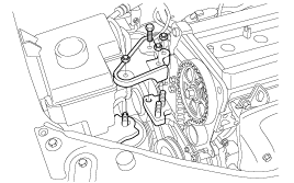
Loosen the coolant pump pulley bolt.
Loosen the alternator bolt.
Remove the coolant pump pulley and belt.
Remove the crankshaft pulley.
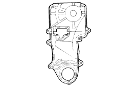
Remove the timing belt cover.
Move the timing belt tensioner pulley toward the coolant pump and temporarily secure it.
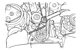
Remove the timing belt.
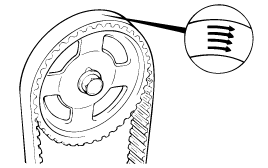
If the timing belt is reused, mark with an arrow to indicate direction of rotation (on the front of the engine) to make sure that the belt is reinstalled in the same direction as before.
Remove the camshaft from the camshaft sprocket.
Remove the camshaft sprocket.
Remove the crankshaft sprocket bolts. Remove the crankshaft sprocket and flange.
Remove the timing belt tensioner.
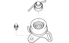
Check the camshaft sporcket, crankshaft sprocket, tensioner pulley, and idler pulley for abnormal wear, cracks, or damage.
Replace as necessary.
Inspect the tensioner pulley and the idler pulley for easy and smooth rotation and check for play or noise.
Replace as necessary.
Replace the pulley if there is a grease leak from its bearing.
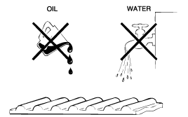
Check the belt for oil or dust deposits. Replace, if necessary.
Small deposits should be wiped away with a dry cloth or paper. Do not clean with solvent.
When the engine is overhauled or belt tension adjusted, check the belt carefully. If any of the following flaws are evident, replace the belt with a new one.
Description | Flaw conditions |
1. Hardened back surface ● Back surface is glossy, non-elastic and so hard that when your fingernail is pressed into it. no mark is produced. |  |
2. Cracked back surface rubber |  |
3. Cracked or separating canvas |  |
 | |
 | |
4. Badly worn teeth (initial stages) ● Canvas on load side of tooth flank worn (Fluffy canvas fibers, rubber gone and color changed to white, and unclear canvas texture) |  |
5. Badly worn teeth (last stage) ● Canvas on load side of tooth flank worn down and rubber exposed (tooth width reduced) |  |
6. Cracked tooth bottom |  |
7. Missing tooth |  |
8. Side of belt badly worn note Normal belt shluld have precisely cut sides as if cut by a sharp knife. | |
9. Side of belt crackeda |
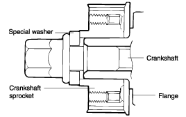
Install the flange and crankshaft sprocket as shown.
Pay close attention to their mounting directions.
Install the camshaft sprocket and tighten the bolt to the specified torque.
Tightening torque
Camshaft sprocket bolt :
80 ~ 100 Nm (800 ~ 1000 kg.cm, 59 ~74 lb.ft)
Install the idler and tighten the idler bolt to the specified torque.
Tightening torque
Idler bolt : 43 ~ 55 Nm (430 ~ 550 kg.cm, 32 ~ 41 lb.ft)
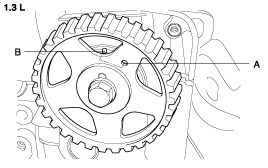
Align the timing marks of the camshaft sprocket (A) and camshaft bearing cap (B).
Then align the timing marks of crankshaft sprocket and front case with the No.1 piston placed at top dead center on its compression stroke as shown in the illustration.
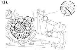
To install the timing belt tensioner, first mount the tensioner, spring, and spacer. Temporarily tighten the bolts. Next, temporarily tighten the tensioner long hole side washer and bolts. Install the bottom end of the spring against the front case as shown in the illustration.
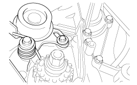
Secure the tensioner, positioned towards the water pump.
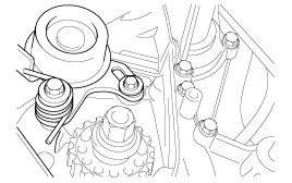
Install the timing belt on the crankshaft sprocket.
(1) Crankshaft sprocket → (2) Timing belt idler → (3) Camshaft sprocket → (4) Timing belt
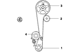
Install the timing belt on the camshaft sprocket. When the timing belt is installed on the camshaft sprocket, make sure that the tension side is tight. Then, check to ensure that when the tension side is tightened by turning the camshaft sprocket in a reverse direction and all timing marks are in line.
Tighten the tensioner bolts.
Turn the crankshaft two turns in its operating direction (clock-wise) and realign the camshaft sprocket timing mark with the top dead center position.
Tightening torque
Tensioner attaching bolt :
20 ~ 27 Nm (200 ~ 270 kg.cm, 15 ~ 20 lb.ft)
Then recheck the belt tension Verify that when the tensioner and the tension side of the timing belt are pushed in horizontally with a moderate force [approx. 49N (11lb)], the timing belt cog end is aprox. 1/2 of the tensioner monting bolt head radius (across flats) away from the bolt head center.
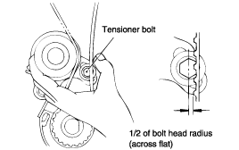
Install the timing belt cover.

Tightening torque
Timing belt cover bolt :
8 ~10 Nm (80 ~ 100 kg.cm, 6 ~ 7 lb.ft)
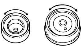
Install the crankshaft pulley. Make sure that the crankshaft sprocket pin fits the small hole in the pulley.
Tightening torque
Crankshaft pulley bolt :
140 ~ 150 Nm (1400 ~ 1500 kg.cm, 103 ~ 111 lb.ft)
Install the fan belt and adjust the belt tension.
Install the water pump pulley.
Install V-belt and adjust the belt tension.
