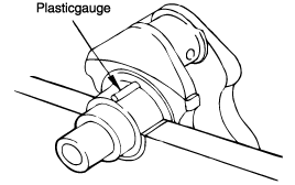
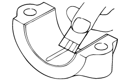
Cut plastic gauge to the same length as the width of the bearing and place ot parallel with the journal, off from the oil holes.

Check the clutch disc contacting surface of the fly wheel for damage and wear. Replace the flywheel if excessively damaged or worn.
Check the clutch disc contacting surface of the fly wheel for runout.
Standard value
Flywheel run-out : 0.1 mm (0.004 in.)
Check the ring gear for damage, crack and wear, and replace if necessary.
Check the crankshaft journals and pins for damage, uneven wear and cracks. Also check oil holes for clogging. Correct or replace any defective part.
Inspect out-of-roundness and taper of crankshaft journal and pin.
Standard value
Crankshaft journal O.D.
1.3 L : 50 mm (1.9685 in.)
1.1 L : 42 mm (1.654 in.)
Crankshaft pin O.D.
1.3 L : 45 mm (1.7717 in.)
1.1 L : 38 mm (1.496 in.)
Crankshaft journal, pin out-of-roundness and taper :
0.01 mm (0.0004 in.) or less
1.3 L
Standard value
Journal oil clearance No. 1, 2, 4, 5 :
0.028 ~ 0.046 mm (0.0011 ~ 0.0018 in.)
Journal oil clearance No. 3 (center) :
0.034 ~ 0.52 mm (0.0013 ~ 0.002 in.)
Pin oil clearance :
0.024 ~ 0.042 mm (0.0009 ~ 0.0017 in.)
1.1 L
Standard value
Journal oil clearance No. 1, 2, 3, 4, 5 :
0.020 ~ 0.038 mm (0.0007 ~ 0.0014 in.)
Pin oil. clearance :
0.012 ~ 0.041 mm (0.0005 ~ 0.0016 in.)
Remove oil, greass and any other dirt from bearings and journals.
Cut plastic gauge to the same length as the width of the bearing and place ot parallel with the journal, off from the oil holes.

Install the crankshaft , bearings, and caps. Tighten them to the specified torques. During this operation, do not turn the crankshaft. Remove the caps.
Measure the width of the plastic gauge at the widest point using the scale printed on the gauge package.
If the clearance exceeds the repair limit, replace the bearing.
Should the standard clearance not be obtained even after bearing replacement, the journal should be fround to a recommended undersize, and a bearing of the same size should be installed.

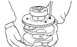
Remove the crankshaft position sensor wheel.
Check the crankshaft position sensor wheel for damage, cracks and wear, and replace if necessary.
Check the clearance between the crankshaft position sensor wheel and the crankshaft position sensor with a depth gage.
Standard value
Clearance between the crankshaft position sensor wheel and crankshaft position sensor :
0.5 ~ 1.5 mm (0.0020 ~ 0.059 in.)
Measure the depth of the top of the crankshaft position sensor wheel teeth and the outside of transaxle housing.
Measure the difference between the crankshaft position sensor length and depth.
The crankshaft position sensor length is the distance between the end of crankshaft position sensor and inner point of contacting face.
