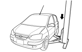
Support the specified portion of the vehicle with a lift.
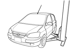
Support the specified portion of the vehicle with a lift.

Drain the power steering fluid.
Remove the front tires (RH/LH).
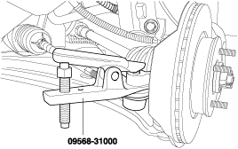
After removing the split pin, disconnect the tie rod from the knuckle by using the special tool.
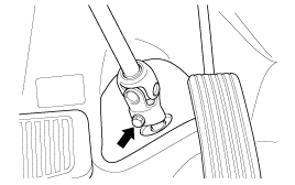
Disconnect the steering shaft assembly from the gear box inside the passenger compartment.
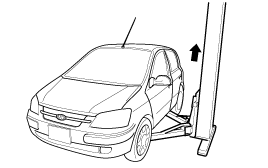
Raise up the vehicle.
Loosen the power steering pressure tube mounting clamp and return tube mounting clamp mounting bolt.
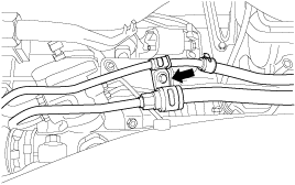
Disconnect the front muffler assembly.
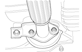
Disconnect the transaxle rear mounting bracket.
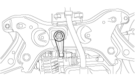
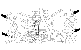
After supporting the crossmember with a transaxle jack, remove the 4 bolts fixing the crossmember.
Disconnect the pressure tube and return tube lifting from the power steering gear box.
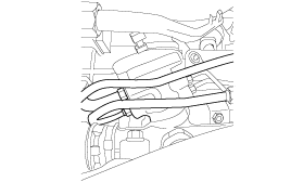
Remove the power steering gear box mounting bolt and clamp.
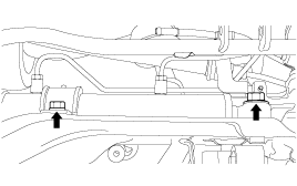
Separate the power steering gear box assembly by pulling it toward the rights side of the vehicle.
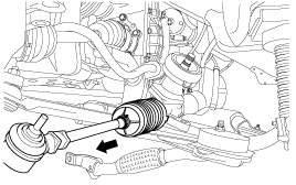
Push in the power steering gear box assembly in the right side of the vehicle.
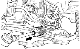
Fix the power steering gear box to the crossmember.

Install the pressure tube and return tube fitting to the power steering gear box.

After raising the crossmember assembly with a transaxle jack, install the crossmember to the body.

Fix the power steering pressure hose and return tube mounting clamp with the bolt.

Fix the transaxle rear mounting clamp.

Fix the front muffler assembly.

Slowly lower the vehicle.
Connect the tie rod to the knuckles (RH/LH)

Install the tires (RH/LH)
Connect the steering shaft to the driver side gear box.

Apply the power steering fluid.
Bleed the air.
Remove the tie rod end from the tie rod.
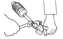
After mounting the tie rod end in a vise, remove the dust cover from the ball joint.
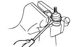
Remove the bellows band.
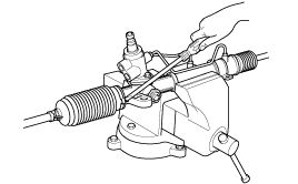
Remove the bellows clip.
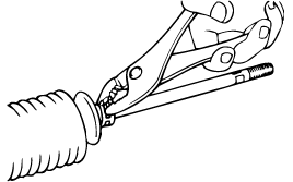
Pull the bellows out toward the tie rod.
Check for rust on the rack when the bellows are replaced.
While moving the rack slowly, drain the fluid from the rack housing.
Unstake the tab washer which fixes the tie rod and rack with a chisel.
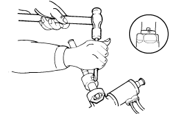
Remove the tie rod from the rack.
Remove the tie rod from the rack, taking care not to twist the rack.
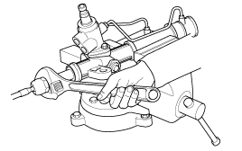
Remove the yoke plug locking nut.
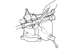
Remove the yoke plug with a 14mm socket.
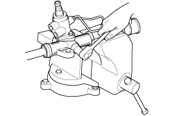
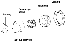
Remove the lock nut, yoke plug, rack support spring, rack support yoke and bushing from the gear box.
Remove the feed tube from the rack housing.
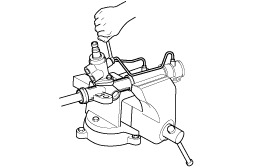
Remove the valve body housing by loosening the two bolts.
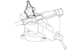
When the end of the circlip comes out of the notched hole of the housing rack cylinder, turn the rack stopper counterclockwise and remove the circlip.
Be careful not to damage the rack.
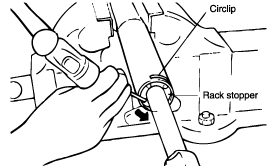
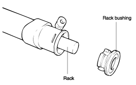
Remove the rack bushing and rack from the rack housing.
Remove the O-ring from the rack bushing.
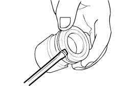
Remove the oil seal from the rack bushing.
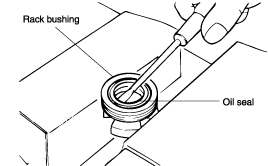
Remove the valve body from the valve body housing with a soft hammer.
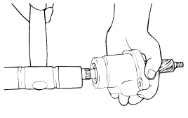
Remove the oil seal and ball bearing from the valve body housing.
Remove the oil seal and O-ring from the rack housing.
Be careful not to damage the pinion valve cylinder bore of the rack housing.
Using the special tool, remove the oil seal and ball bearing from the valve body housing.
Rack
Check for rack tooth face damage or wear
Check for oil seal contact surface damage
Check for rack bending or twisting
Check for oil seal ring damage or wear
Check for oil seal damage or wear
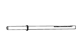
Pinion valve
Check for pinion gear tooth face damage or wear
Check for oil seal contact surface damage
Check for seal ring damage or wear
Check for oil seal damage or wear
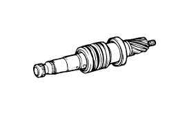
Bearing
Check for seizure or abnormal noise during a bearing rotation
Check for excessive play
Check for missing needle bearing rollers
Others
Check for damage of the rack housing cylinder bore
Check for boot damage, cracking or aging
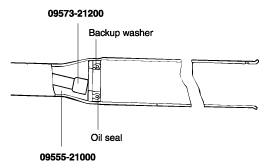
Apply the specified fluid to the entire surface of the rack oil seal.
Recommended fluid : PSF-3
Install the oil seal to the specified position in the rack housing.
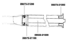
Apply the specified fluid to the entire surface of the rack bushing oil seal.
Recommended fluid : PSF-3
Install the oil seal in the rack bushing.
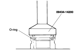
Apply the specified fluid to the entire surface of the O-ring and install it in the rack bushing.
Apply the specified grease to the rack teeth.
Recommended grease :
Multipurpose grease SAE J310a, NLGI #2 EP
Do not plug the vent hole in the rack with grease.

Insert the rack into the rack housing and push in the rack bushing until it is aligned with the notched hole of the rack housing, then install it.
Using a special tool, install the oil seal and the ball bearing in the valve body housing.
After applying the specified fluid and grease to the pinion valve assembly, install it in the rack housing assembly.
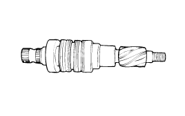
After applying the specified fluid to the oil seal, install it in the rack housing, and fix the valve body assembly and O-ring in the gear box.

Install the tie rod and punch on a point over the tie rod with a chisel.

Install the bushing, rack support yoke, rack support spring and yoke plug in the order shown in the illustration. Apply semi-drying sealant to the threaded section of the yoke plug before installation.

With the rack placed in the center position, attach the yoke plug to the rack housing. Tighten the yoke plug to 12 Nm (120 kg·cm, 8.9 lb·ft), with a 14mm socket. Loosen the yoke plug approximately from 30° to 60° and tighten the yoke nut to the specified torque.
Tightening torque
50~70 Nm (500~700 kg·cm, 37~52 lb·ft)
Tighten the feed tube to the specified torque and install the mounting rubber using adhesive.
Apply the specified grease to the bellows mounting position (fitting groove) of the tie rod.
Recommended grease : Silicone grease
Install the new attaching band to the bellows.
When the bellows are installed, a new band must be used.
Install the bellows in position, taking care not to twist it.
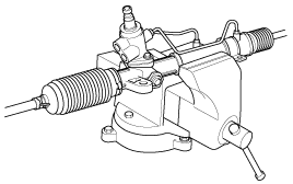
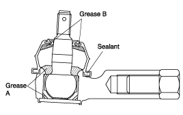
Fill the dust cover inner side and lip with the specified grease, and fix the dust cover in position with the clip ring attached in the groove of the tie rod end.
Recommended grease
A : POLY LUB GLY 801K or equivalent
B : SHOWA SUNLIGHT MB2 or equivalent
Dust cover inner side and lip : THREE BOND
Install the tie rod to the tie rod end.

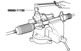
Check for total pinion preload.
Rack
Check for rack tooth face damage or wear
Check for oil seal contact surface damage
Check for rack bending or twisting
Check for oil seal ring damage or wear
Check for oil seal damage or wear

Pinion valve
Check for pinion gear tooth face damage or wear
Check for oil seal contact surface damage
Check for seal ring damage or wear
Check for oil seal damage or wear

Bearing
Check for seizure or abnormal noise during a bearing rotation
Check for excessive play
Check for missing needle bearing rollers
Others
Check for damage of the rack housing cylinder bore
Check for boot damage, cracking or aging