2.
Probe(+) : PCSV harness connector NO2.
Probe(-) : Chassis ground.
The evaporative emission control system prevents hydrocarbon (HC) vapors from the fuel tank from escaping into the atmosphere where they could form photochemical smog. Gasoline vapors are collected in the charcoal canister. The ECM controls the Purge Control Solenoid Valve (PCSV) to purge any collected vapors from the canister back to the engine for combustion. This valve is actuated by the purge control signal from the ECM and controls fuel vapor from the canister to the intake manifold.
The ECM sets DTC P0444 if the ECM detects that the PCSV control line is open.
Item | Detecting Condition | Possible cause |
Monitoring Strategy | ● Signal check low , Signal interruption , Rationality check | ● Open in sensor signal line ● Open in sensor power line ● Short in sensor signal line |
Threshold value | ● Short circuit to GND or Wire disconnected | |
Enable Conditions | ||
Diagnostic Time | ||
MIL on condition | ● 2 driving cycle |
Service standard
Idle : 0 %
1000~3000 rpm : 1.5 ~ 35 %
Service standard
Idle : 0 %
1000~3000 rpm : 1.5 ~ 35 %
This inspection procedure is recommended when service data with scan tool in not enough.
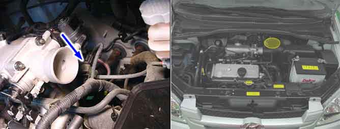
Start engine and warm up to operating temperature.
Probe(+) : PCSV harness connector NO2.
Probe(-) : Chassis ground.
This is waveform measured at terminal 2 of PCSV under no-load,1500 RPM.
The voltage at point ① is 14 V.
Possible cause:No power supply or open in PCSV.
Point ② is a surge voltage when power TR is off and about 45 V.
Periode ③ is the duration when PCSV operates and usually operating duty value is about 15 % in 2000RPM.
Periode ④ is duty per 1Hz and ON-OFF ratio of TR in ECM.
If the PCSV’s waveform shows simirally with that of figure above,it is likely to be normal PCSV.
In case there is no symptom and wrong data but DTC is shown
The problem may be intermittent so slightly shake the connector and harness vertically and horizontally to check if there is any data changes
If the data changes normally, the problem was intermittent so erase DTC and verify the same DTC reoccure.
Go to "Terminal and Connector inspection" procedure.
In case there is symptom and wrong data with DTC
Check open,short or connector’s connection for PCSV.
Check the deterioration of PCSV performance.
Go to "Signal circuit inspection" procedure.
