3.
Has a problem been found?
YES
a.
Repair as necessary and then go to "Verification of Vehicle Repair" procedure.
NO
a.
Go to "Signal Circuit Inspection" procedure.
Many malfunctions in the electrical system are caused by poor harness and terminals. Faults can also be caused by inerference from other electrical systems, and mechanical or chemical damage.
Thoroughly check all connectors (and connections) for looseness, bending, corrosion, contamination, deterioration, and/or damage.
Has a problem been found?
YES
Repair as necessary and then go to "Verification of Vehicle Repair" procedure.
NO
Go to "Signal Circuit Inspection" procedure.
Ignition "OFF".
Connect Scantool to Data Link Connector(DLC) and then start engine.
Select "SCOPEMETER FUNCTION"on scantool and then accelerate Engine.
Measure output signal between terminal "12"of EPS CM harness connector and chassis ground.
Specification :
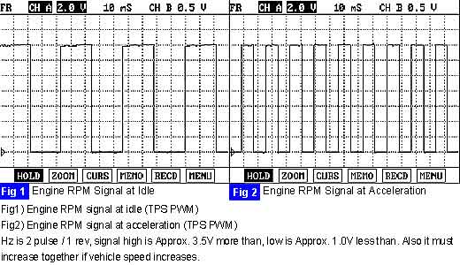
Is tachometer output signal within specifications?
YES
Substitute with a known-good EPS CM and check for proper operation.
If the problem is corrected, replace EPS CM and then go to "Verification of Vehicle Repair" procedure.
NO
Go to "Check for open/short in signal harness" as below.
Ignition "OFF"
Disconnect MC21(or MC121)connector and EPS CM connector.
Measure resistance between terminal "8"of MC21(or MC121)connector and terminal "12"of EPS CM harness connector.
Specification : Approx. 0 Ω
Is the resistance measured within specifications?
YES
Check for short to ground in signal harness.
→ If it is normal, go to "Component Inspection" procedure.
→ If it is abnormal, repair as necessary and then go to "Verification of Vehicle Repair" procedure.
NO
Check for open/short in signal harness.
Repair as necessary and then go to "Verification of Vehicle Repair" procedure.
