
Perform troubleshooting with the following Workflow.
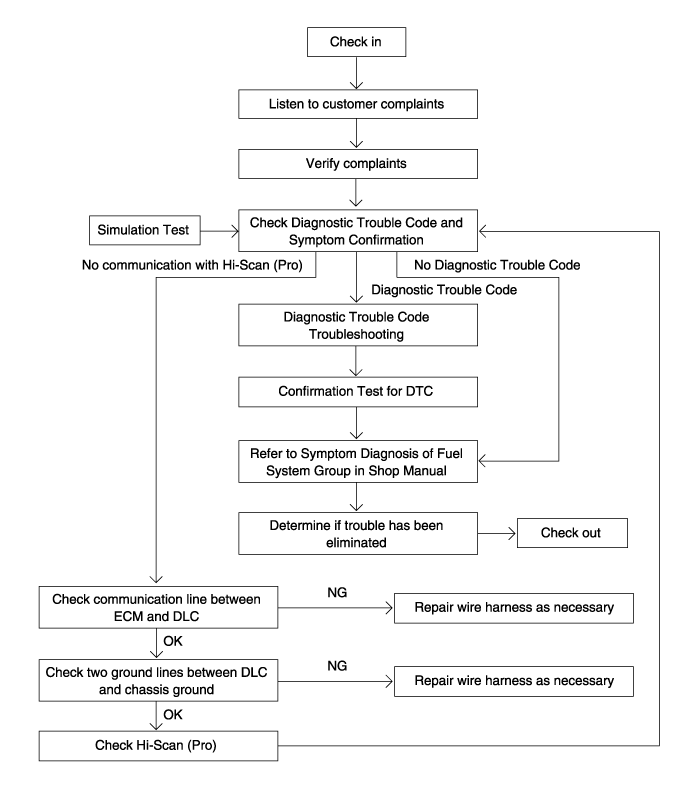
Most of the fuel and emission control system is electrically controlled, often making it difficult to diagnose problems in the system, especially intermittent problems. Before undertaking actual checks, take a few minutes to talk with a customer who approaches with a complaint, the customer is often a good source of information on such problems, especially intermittent ones. Through talking with the customer, one can find out what the symptoms are and under what conditions they occur.Most intermittent malfunctions occur under certain conditions. If the conditions can be identified, it is easier to find the cause.
Ask the customer about malfunctions; driving conditions, weather, frequency of occurrence, what it sounds like, etc.
Determine the conditions: typically almost intermittent malfunctions occur under conditions such as vibration, temperature, moisture, and/or poor connections. From customer’s complaints, it should be reasoned which condition is influenced.
Perform simulation test.
Sometimes the most difficult case in troubleshooting is that the problem symptom occurred previously does not appear again. In such case, this simulation test is used effectively for repairing intermittent malfunctions.
Vibration
Shake slightly connector and wiring harness up and down and right and left.
Vibrate slightly sensors or actuators.
Heat
Heat components likely caused malfunction with a hair dryer or others.
In this test, temperature is limited to keep from damaging components and do not heat ECM directly.
Water sprinkling
Sprinkle water onto vehicle to simulate a rainy day or in a high humidity condition.
In this test, do not sprinkle water directly onto engine compartment or electronic component.
Electrical loads
Turn on all electrical systems to simulate the excessive electrical loads.
This troubleshooting manual consists of six major service categories, Description, DTC (Diagnostic Trouble Code) Detecting Condition, Specification, Schematic Diagram, Signal Waveform, and Inspection Procedure by DTC.
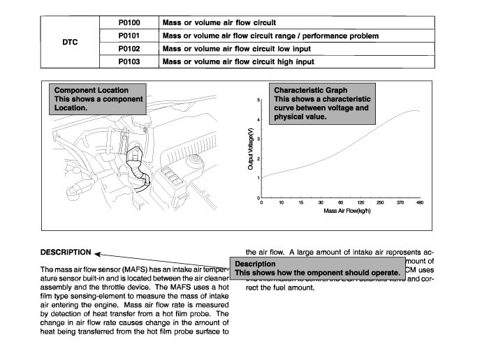
This section provides how the component should operate. Also, this section shows component location and its characteristic curve.
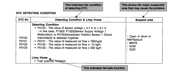
This section contains DTC detecting condition and possible cause.
This section shows specifications of sensors, actuators, or specified system.

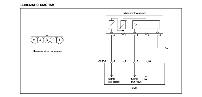
These diagrams show how components work, such as electrical current paths from power source to ground and ECM. It is important to fully understand how a circuit works prior to troubleshooting.
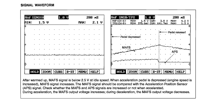
This section shows the waveform of major sensors or actuators, which is used for only reference information.
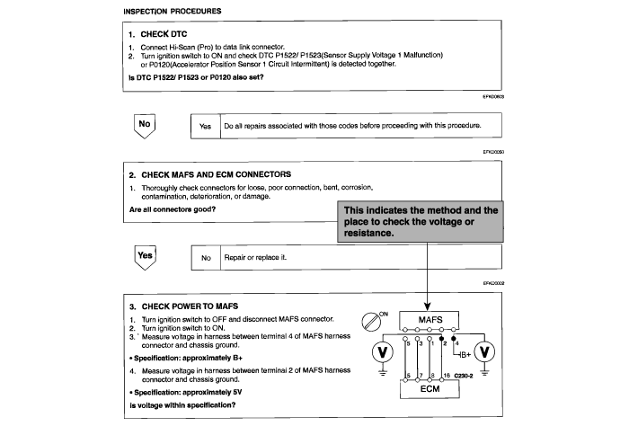
This section shows an inspection procedure by DTC.
Erase the diagnostic trouble codes from ECM memory using Hi-Scan (Pro).
Start engine and warm it up to normal operating temperature, and then run at 2500 rpm for three minutes.
Verify that no diagnostic trouble codes are recorded.
If diagnostic trouble codes are recorded, refer to diagnostic trouble code troubleshooting.

Terminal | Signal | Connected To |
1 | Battery (-) | Battery Ground |
2 | Battery (-) | Battery Ground |
3 | Battery (-) | Battery Ground |
4 | Battery (+) via fuse(10A) | Main Relay |
5 | Battery (+) via fuse(20A) | Main Relay |
6 | Not used | - |
7 | Not used | - |
8 | Not used | - |
9 | CAN(Low) | TCM |
10 | CAN(High) | TCM |
11 | SMARTRA immobilizer signal | SMARTRA |
12 | Fuel consumption signal | Trip Computer |
13 | Engine control relay control | Engine Control Relay(Main Relay) |
14 | Not used | - |
15 | GLOW plug relay control | GLOW Plug Relay |
16 | EGR actuator control | EGR Solenoid Valve |
17 | Electric fuel pump control | Electric Fuel Pump Relay |
18 | Throttle plate actuator control | Throttle Plate Actuator |
19 | Condenser fan relay control | Condenser Fan Relay |
20 | Radiator fan relay control | Radiator Fan Relay |
21 | A/C compressor relay control | A/C Compressor Relay |
22 | Not used | - |
23 | Auxiliary water heater relay control | Auxiliary Water Heater Relay |
24 | Immobilizer indicator lamp control | Immobilizer Indicator Lamp |
25 | Not used | - |
26 | Not used | - |
27 | Not used | - |
28 | Not used | - |
29 | Not used | - |
30 | Not used | - |
31 | Not used | - |
32 | Not used | - |
33 | Not used | - |
34 | Not used | - |
35 | Not used | - |
36 | Not used | - |
37 | Not used | - |
38 | Not used | - |
39 | Not used | - |
40 | Not used | - |
41 | Not used | - |
42 | Not used | - |
43 | Not used | - |
44 | Not used | - |
45 | Not used | - |
46 | Not used | - |
47 | Engine speed signal to Tachometer | Tachometer |
48 | Diagnosis K-Line | Scan Tool Connector |
49 | Vehicle speed sensor signal | Vehicle speed sensor |
50 | Not used | - |
51 | A/C pressure switch signal | A/C Pressure Switch |
52 | A/C medium switch signal | A/C Medium Switch |
53 | Not used | - |
54 | Redundant brake switch signal | Brake Switch |
55 | Not used | - |
56 | Not used | - |
57 | Not used | - |
58 | Ignition switch ON/OFF signal | Ignition Switch |
59 | Brake switch signal | Brake Switch |
60 | A/C ON switch signal | A/C Switch |
61 | Clutch switch signal(MT) | Clutch Switch |
62 | Not used | - |
63 | Not used | - |
64 | Not used | - |
65 | Not used | - |
66 | Not used | - |
67 | Not used | - |
68 | Not used | - |
69 | Not used | - |
70 | Not used | - |
71 | Not used | - |
72 | Not used | - |
73 | Not used | - |
74 | Not used | - |
75 | Not used | - |
76 | Acceleration pedal sensor ground 1 | Acceleration Pedal Sensor |
77 | Acceleration pedal sensor signal 1 | Acceleration Pedal Sensor |
78 | Acceleration pedal sensor supply 1 | Acceleration Pedal Sensor |
79 | Acceleration pedal sensor ground 2 | Acceleration Pedal Sensor |
80 | Acceleration pedal sensor signal 2 | Acceleration Pedal Sensor |
81 | Acceleration pedal sensor supply 2 | Acceleration Pedal Sensor |
Terminal | Signal | Connected To |
1 | Fuel temperature sensor signal | Fuel Temperature Sensor |
2 | Fuel temperature sensor ground | Fuel Temperature Sensor |
3 | Coolant temperature sensor signal | Coolant Temperature Sensor |
4 | Coolant temperature sensor ground | Coolant Temperature Sensor |
5 | Air temperature sensor signal | Air Temperature Sensor |
6 | SMARTRA immobilizer ground | Ground |
7 | Mass Air flow sensor ground | Mass Air Flow Sensor |
8 | Mass Air flow sensor signal | Mass Air Flow Sensor |
9 | Rail pressure sensor supply | Rail Pressure Sensor |
10 | Rail pressure sensor signal | Rail Pressure Sensor |
11 | Rail pressure sensor ground | Rail Pressure Sensor |
12 | Not used | - |
13 | Not used | - |
14 | Not used | - |
15 | Not used | - |
16 | Mass Air flow sensor supply | Mass Air Flow Sensor |
17 | Not used | - |
18 | Crankshaft position sensor signal(+) | Crankshaft Position Sensor |
19 | Crankshaft position sensor signal(-) | Crankshaft Position Sensor |
20 | Crankshaft position sensor shield | Crankshaft Position Sensor |
21 | Not used | - |
22 | Camshaft position sensor signal | Camshaft Position Sensor |
23 | Camshaft position sensor ground | Camshaft Position Sensor |
24 | Not used | - |
25 | Not used | - |
26 | Not used | - |
27 | Fuel regulator high side | Fuel Regulator |
28 | Fuel regulator low side | Fuel Regulator |
29 | MIL control | MIL |
30 | Glow time indicator lamp control | Glow Time Indicator Lamp |
31 | Not used | - |
32 | Not used | - |
33 | Injector (cylinder No.1) | Injector (cylinder No.1) |
34 | Not used | - |
35 | Not used | - |
36 | Injector bank for cylinder No.1 | Injector (cylinder No.1) |
37 | Injector bank for cylinder No.2 and No.3 | Injector (cylinder No.2 and No.3) |
38 | Not used | - |
39 | Injector (cylinder No.3) | Injector (cylinder No.3) |
40 | Injector (cylinder No.2) | Injector (cylinder No.2) |
DTC NO. | DESCRIPTION | MIL | SEE PAGE |
P0101 | Mass or Volume Air Flow Circuit Range / Performance Problem | ○ | FL-28 |
P0102 | Mass or Volume Air Flow Circuit Low Input | ○ | FL-28 |
P0103 | Mass or Volume Air Flow Circuit High Input | ○ | FL-28 |
P0104 | Mass or Volume Air Flow Circuit Intermittent | ○ | FL-28 |
P0107 | Atmospheric Pressure Circuit Low Input | △ | FL-34 |
P0108 | Atmospheric Pressure Circuit High Input | △ | FL-34 |
P0112 | Intake Air Temperature Circuit Low Input | △ | FL-35 |
P0113 | Intake Air Temperature Circuit High Input | △ | FL-35 |
P0116 | Engine Coolant Temperature Circuit Range / Performance | △ | FL-40 |
P0117 | Engine Coolant Temperature Circuit Low Input | △ | FL-40 |
P0118 | Engine Coolant Temperature Circuit High Input | △ | FL-40 |
P0123 | Accelerator Position Sensor 1 Circuit High Input | ○ | FL-46 |
P0124 | Accelerator Pedal Sensor 1 Circuit Intermittent | ○ | FL-46 |
P0182 | Fuel Temp Sensor A Circuit Low Input | △ | FL-51 |
P0183 | Fuel Temp Sensor A Circuit High Input | △ | FL-51 |
P0191 | Fuel Rail Pressure Sensor Circuit Range/Performance | ○ | FL-56 |
P0192 | Fuel Rail Pressure Sensor Circuit Low Input | ○ | FL-56 |
P0193 | Fuel Rail Pressure Sensor Circuit High Input | ○ | FL-56 |
P0194 | Fuel Rail Pressure Sensor Circuit Intermittent | ○ | FL-56 |
P0221 | Accelerator Position Sensor 2 Circuit Range/Performance Problem | ○ | FL-62 |
P0223 | Accelerator Position 2 Circuit High Input | ○ | FL-62 |
P0224 | Accelerator Pedal Sensor 2 Circuit Intermittent | ○ | FL-62 |
P0231 | Electric Fuel Pump Circuit Low | △ | FL-67 |
P0232 | Electric Fuel Pump Circuit High | △ | FL-67 |
P0261 | Cylinder 1 - Injector Circuit Low(Over Current Low Side) | ○ | FL-72 |
P0262 | Cylinder 1 - Injector Circuit High(Over Current High Side) | ○ | FL-72 |
P0263 | Cylinder 1 - Injector Circuit Balance(Load Drop is Detected) | ○ | FL-72 |
P0264 | Cylinder 2 - Injector Circuit Low(Over Current Low Side) | ○ | FL-76 |
P0265 | Cylinder 2 - Injector Circuit High(Over Current High Side) | ○ | FL-76 |
P0266 | Cylinder 2 - Injector Circuit Balance(Load Drop is Detected) | ○ | FL-76 |
P0267 | Cylinder 3 - Injector Circuit Low(Over Current Low Side) | ○ | FL-80 |
P0268 | Cylinder 3 - Injector Circuit High(Over Current High Side) | ○ | FL-80 |
P0269 | Cylinder 3 - Injector Circuit Balance(Load Drop is Detected) | ○ | FL-80 |
P0336 | Crankshaft Position Sensor A Circuit Range/Performance | △ | FL-84 |
P0341 | Camshaft Position Sensor A Circuit Range/Performance(Single Sensor) | △ | FL-84 |
P0343 | Camshaft Position Sensor A Circuit High Input | △ | FL-84 |
P0401 | Exhaust Gas Recirculation Flow Insufficent Detected | ○ | FL-91 |
P0402 | Exhaust Gas Recirculation Flow Excessive Detected | ○ | FL-91 |
P0405 | Exhaust Gas Recirculation Flow A Circuit Low | ○ | FL-91 |
P0406 | Exhaust Gas Recirculation Sensor A Circuit High | ○ | FL-91 |
P0501 | Vehicle Speed Sensor Range / Performance | △ | FL-97 |
P0503 | Vehicle Speed Sensor Intermittent/High | △ | FL-97 |
P0562 | System Voltage Low | △ | FL-101 |
P0563 | System Voltage High | △ | FL-101 |
P0601 | Internal Control Module Memory Check Sum Error | ○ | FL-103 |
P0602 | Control Module Programming Error | ○ | FL-103 |
P0603 | Internal Control Module Keep Alive Memory Error | ○ | FL-103 |
P0703 | Stop Lamp(Brake) Switch Malfunction | △ | FL-104 |
P0704 | Clutch Pedal S/W Malfunction | △ | FL-109 |
P1182 | Fuel Pressure Regulator Short | ○ | FL-113 |
P1183 | Fuel Pressure Regulator Open | ○ | FL-113 |
P1184 | Fuel Pressure Regulator Power Stage Error | ○ | FL-113 |
P1185 | Maximum Pressure Exceeded | ○ | FL-117 |
P1186 | Minimum Pressure at Engine Speed Too Low | ○ | FL-117 |
P1187 | Regulator Valve Stick | ○ | FL-117 |
P1188 | Leakage | ○ | FL-117 |
P1189 | Governor Deviation at Engine Speed Too high | ○ | FL-117 |
P1190 | Throttle Plate Actuator Malfunction | △ | FL-121 |
P1300 | Synchronization Error (CKP/CMP plausibility) | △ | FL-84 |
P1321 | Glow Indicator Lamp Short | △ | FL-126 |
P1322 | Glow Indicator Lamp Open | △ | FL-126 |
P1326 | Glow Plug Relay Short | △ | FL-129 |
P1327 | Glow Plug Relay Open | △ | FL-129 |
P1522 | Sensor Supply Voltage 1 Below Lower Limit | △ | FL-134 |
P1523 | Sensor Supply Voltage 1 Above Upper Limit | △ | FL-134 |
P1524 | Sensor Supply Voltage 2 Below Lower Limit | △ | FL-136 |
P1525 | Sensor Supply Voltage 2 Above Upper Limit | △ | FL-136 |
P1616 | Main Relay Malfunction | ○ | FL-138 |
P1620 | A/Con Comp. Relay Short | △ | FL-142 |
P1621 | A/Con Comp. Relay Open | △ | FL-142 |
P1624 | Radiator Cooling Fan Circuit Malfunction (Low Circuit) | △ | FL-147 |
P1625 | Radiator Cooling Fan Circuit Malfunction (High Circuit) | △ | FL-147 |
P1628 | Main Condensor Fan Curcuit Low | △ | FL-152 |
P1629 | Main Condensor Fan Circuit High | △ | FL-152 |
P1634 | Water Heater Relay Malfunction | △ | FL-156 |
P1636 | Voltage Regulator for Injector Malfunction | △ | FL-161 |
P1638 | Microcontroller Malfunction | △ | FL-162 |
P1639 | A/D Converter Monitoring Malfunction | △ | FL-163 |
P1646 | Capacitor Voltage Malfunction-Booster Voltage Too High | △ | FL-164 |
P1647 | Capacitor Voltage Malfunction-Booster Voltage Too Low | △ | FL-164 |
P1652 | IG S/W Malfunction | △ | FL-165 |
P1653 | Error Check After IG-OFF Malfunction | △ | FL-168 |
P1690 | Smartra/Antena Error | △ | FL-169 |
P1692 | Immo indicator lamp | △ | FL-173 |
P1693 | Transponder Error | △ | FL-169 |
P1695 | EEPROM Error | △ | FL-169 |
P1696 | Authentication Not Successful | △ | FL-169 |
P1697 | Invalid Tester Request | △ | FL-169 |
P1698 | EEPROM Faulty For Key ID Blocks & Immo. Data Block | △ | FL-169 |
○ : MIL ON and means fault code memory
△ : MIL OFF and means fault code memory