Using the special tool, Valve Spring Remover and Installer, remove the retainer lock. Next, remove the spring retainer, vlave spring, spring seat and valve.
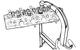
Keep these parts in order so that they can be rein-stalled in their original positions.
Using the special tool, Valve Spring Remover and Installer, remove the retainer lock. Next, remove the spring retainer, vlave spring, spring seat and valve.

Keep these parts in order so that they can be rein-stalled in their original positions.
Remove the valve stem seals with pliers, and discard them.
Do not reuse the valve stem seals.
Check the valve spring free length and tension. If they exceed the service limit, replace the spring.
Using a square, test the squareness of each spring.
If a spring is excessively out of square, replace it.
Standard vlaue
Free height
1.3 L : 42.03 mm (1.655 in.)
1.1 L : 40.50 mm (1.594 in.)
Load
1.3 L : 24.7 kg at 34.5 mm
1.1 L : 15.60 ± 0.9 kg/32.0 mm
Out of square : 1.5° or less
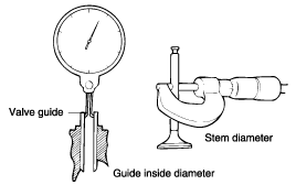
Check the valve stem-to-guide clearance. If the clearance exceeds the service limit, replace the vlave guide with the next oversize part.
Standard vlaue
Intake
1.3 L : 0.030 ~ 0.060 mm (0.0012 ~ 0.0024 in.)
1.1 L : 0.020 ~ 0.047 mm (0.0008 ~ 0.0018 in.)
Exhaust
1.3 L : 0.035 ~ 0.065 mm (0.0014 ~ 0.0026 in.)
1.1 L : 0.050 ~ 0.082 mm (0.0019 ~ 0.0032 in.)
Size mm (in.) | Size mark | Cylinder head hole size mm (in.) |
0.05 (0.002) O.S. | 5 | 11.05 ~ 11.058 (0.435 ~ 0.4354) |
0.25 (0.010) O.S. | 25 | 11.25 ~ 11.258 (0.429 ~ 0.4432) |
0.50 (0.020) O.S. | 50 | 11.50 ~ 11.508 (0.4528 ~ 0.4531) |
Size mm (in.) | Size mark | Cylinder head hole size mm (in.) |
0.05 (0.002) O.S. | 5 | 10.05 ~ 10.068 (0.395 ~ 0.396) |
0.25 (0.010) O.S. | 25 | 1.025 ~ 10.268 (0.403 ~ 0.404) |
0.50 (0.020) O.S. | 50 | 10.50 ~ 10.518 (0.413 ~ 0.414) |
The valve guide is installed using a press fit. Using Value Guide installer (09221-21200 A/B (1.3L), 09222-02100 (1.1L)) or suitable tool, replace the valve guide described in the following procedure.
Using the Valve Guide installer push rod, push the valve guide out toward the cylinder block with a press.
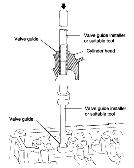
Machine the valve guide insert hole in the cylinder head to the specified oversize of the new valve guide.
Using the Valve Guide installer or suitable tool, press fit the valve guide. Using the vlalve guide installer makes it possinle to press fit the valve guide to a predetermined height. Install the vlave guide from the top of the cylinder head. Note that intake and exhaust valve guides differ in length.
After installing the valve guides, insert new valves and check the clearance.
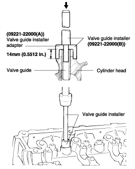
Whenever valve guides are replaced, check for valve-to-seat contact, and recondition the valve seats as necessary.
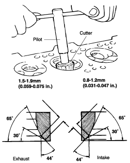
Any valve seat insert that has been worn over the service limit should be removed at normal temperature after cutting away most of the insert wall, using valve seat cutters, as shown in Fig A.
After removing the seat insert, machine the seat insert bore using a reamer or a cutter. Cut to the size shown in the table.
Heat the cylinder head to about 250°C (480°F) and press in the oversize seat insert. The oversize seat insert should be at normal room temperature for installation. After installing a new valve seat insert, resurface the valve seat using the same procedure described in the first paragraph of "Valve Seat Insert" (above).
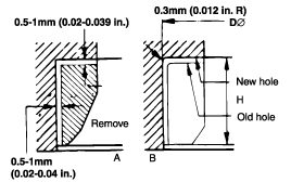
Description | Size mm (in.) | Size mark | Seat insett height H mm (in.) | Cylinder head I.D. mm (in.) |
Intake valve seat insert | 0.3 (0.012) O.S. | 30 | 5.1~5.3 (0.201~0.2069) | 28.80~28.821(1.134~1.135) |
0.6(0.024) O.S. | 60 | 5.4~5.6 (0.213~0.220) | 29.10~29.121(1.146~1.147) | |
Exhaust valve seat | 0.3 (0.012) O.S. | 30 | 5.9~6.1 (0.232~0.240) | 34.30~34.325(1.350~1.351) |
0.6 (0.024) O.S. | 60 | 6.2~6.4(0.244~0.252) | 34.60~34.625(1.362~1.363) |
Description | Size mm (in.) | Size mark | Seat insett height H mm (in.) | Cylinder head I.D. mm (in.) |
Intake valve seat insert | 0.3 (0.012) O.S. | 30 | 6.2~6.4 (0.244~0.252) | 24.30~24.321(0.957~0.958) |
0.6(0.024) O.S. | 60 | 6.5~6.7 (0.0256~0.264) | 24.60~24.621(0.968~0.969) | |
Exhaust valve seat | 0.3 (0.012) O.S. | 30 | 6.2~6.4 (0.244~0.252) | 29.30~29.321(1.153~1.154) |
0.6 (0.024) O.S. | 60 | 6.5~6.7(0.256~0.264) | 29.60~29.621(1.165~1.166) |
Check each valve for wear, damage and distortion of head and stem at B. Repair or correct, if necessary. If stem end A is pitted or worn, resurface as necessary. This correction must be limited to a minimum. Also resurface the valve face.
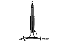
MARGIN
Standard value
Intake
1.3 L : 1.1 mm (0.043 in.)
1.1 L : 0.8 mm (0.031 in.)
Exhaust
1.3 L : 1.4 mm (0.055 in.)
1.1 L : 1.2 mm (0.047 in.)
Limit
Intake
1.3 L : 0.8 mm (0.031 in.)
1.1 L : 0.5 mm (0.019 in.)
Exhaust
1.3 L : 1.1 mm (0.043 in.)
1.1 L : 0.9 mm (0.035 in.)
Thoughly clean each part before assembly.
Apply engine oil to sliding and rotating parts.
After installing the spring seat, fit the stem seal into the valve guide.
To install, fit the seal in by lightly tapping the Special Tool, Valve Stem Oil Seal Installer.
The seal is installed in the specified position by means of the special tool. Incorrect installation of the seal will adversely affect the lip I.D. and eccentricity, resulting in oil leaking down the valve guides. Therefore, when installing, be careful not to twist the seal. Do not reuse old stem seals.
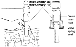
Apply engine oil to each valve. Insert the valves into the valve guides. Avoid using force when inserting the valve into the seal. After insertion, check to see if the valve moves smoothly.
Install springs and spring retainers. Valve springs should be installed with the enamel coated side toward the valve spring retainer.
Valve springs should be installed with the enamel coated side toward the valve spring retainer.
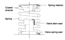
Using special tool, Valve Spring Remover and Installer, compress the spring. Be careful that the valve stem seal is not distorted by the bottom of the retainer. Then install the retainer locks. After installation of the valves, make certain that the retainer locks are properly installed.

Install the cylinder head. Refer to "Cylinder Head"