2.
Channel 1 probe(+) : Injector harness connector NO2.
Channel 1 probe(-) : Chassis ground.
Based on information from various sensors, the ECM decides the fuel injection amount. The fuel injector is a solenoid-operated valve and the fuel injection amount is controlled by length of time the fuel injector is held open. The ECM controls each injector by grounding the control circuit. When the ECM energizes the injector by grounding the control circuit, the circuit voltage should be low (theoretically 0V) and the fuel is injected. When the ECM de-energizes the injector by opening control circuit, the fuel injector is closed and circuit voltage should be peak for a moment.

The ECM sets DTC P0268 if the ECM detects that injector control line is short to battery.
Item | Detecting Condition | Possible cause |
Monitoring Strategy | ● Signal check High | ● Short to battery ● Bad injector |
Threshold value | ● Short circuit to Batt. | |
Enable Conditions | ||
Diagnostic Time | ● Continuous | |
MIL on condition | ● 2 driving cycle |
Service standard
In idling: 2.2 ~ 5.0ms
2500 rpm : 2.0 ~ 5.0ms
Specification
In idling: 2.2 ~ 5.0ms
2500 rpm : 2.0 ~ 5.0ms
Start engine and warm up to operating temperature.
Channel 1 probe(+) : Injector harness connector NO2.
Channel 1 probe(-) : Chassis ground.
This figure shows the voltage waveform on channel1 in idling.
At point ①,the measured voltage should be nearly battery voltage.
The measured voltage at point ② is the surge voltage and is approximately 56V.
The measured voltage at point ③ is below 1V and the periode is between 1.8ms and 4ms in idling when warmed up condition.
If the injector’s waveform shows simirally with that of figure above,it is likely to be normal injector.
In case there is no symptom and wrong data but DTC is shown
The problem may be intermittent so slightly shake the connector and harness vertically and horizontally to check if there is any data changes
If the data changes normally, the problem was intermittent so erase DTC and verify the same DTC reoccure.
Go to "Terminal and Connector inspection" procedure.
In case there is symptom and wrong data with DTC
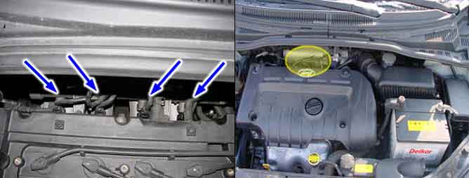
Check open,short or connector’s connection for injector.
Check the deterioration of injector performance.
Go to "Signal circuit inspection" procedure.
