ARE THE WIRES O.K ? & ARE THE CONNECTIONS O.K ?
YES
Go to "Signal Circuit Inspection" procedure.
NO
Repair as necessary and go to " Verification of Vehicle Repair " procedure
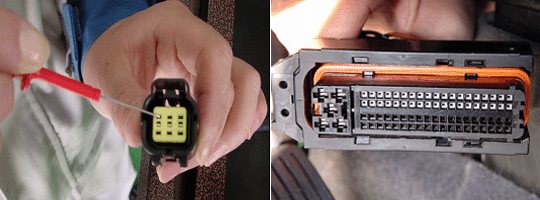
Check for damaged harness and terminals including rubber seals :
-. contact resistance, oxidation, corrosion, bent or broken terminals
-. harness connector connection, loose wires etc.
Check for poor connection between ECM and component :
-. backed out terminal, improper mating, broken locks and poor terminal to wire connection
ARE THE WIRES O.K ? & ARE THE CONNECTIONS O.K ?
YES
Go to "Signal Circuit Inspection" procedure.
NO
Repair as necessary and go to " Verification of Vehicle Repair " procedure
DTCs listed below are stored in the scan tool
P0221/P0223/P0224
Check items with the scan tool and the multimeter
① Wiring harness inspection
② Waveform from APS 1 and APS 2
③ Sensor supply voltage from ECM
Specification :
Resitance : below 1 Ω for open in the wire
Resitance : infinite for short to ground in the wire
Voltage : below 0.5V for short to power in the wire
Sensor supply voltage : Approx. 5V
Resitance : 1.7 ㏀ ±0.8 ㏀ at 20℃(68℉)
Refer to the component and full circuit for connector configrations details
Connect the CH A,B probe of scan tool to the APS 1 terminal 2 and the APS 2 terminal 3 individually after turning the ignition switch OFF and then start the engine
Check the APS 1 and APS 2 signal waveform when depressing the accelerator pedal fully one time.
ARE THERE APS 1 AND APS 2 SIGNAL WAVEFORM PRORERLY DISPLAYED ?
YES
Intermittent failure, system is O.K at this time.
Check for poor connections or losse wire at the APS and the ECM.
NO
Replace the APS assembly if the waveform signala are not a normal curve between the APS 1 and the APS 2
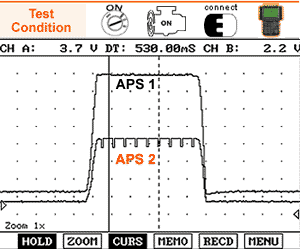
WAVEFORM ANALYSIS
If you want the APS 1 or the APS 2 signal to check with the Mass air flow meter sensor signal, Go to " DTC 0103 " This test should be inspected after depressing the HOLD mode from run after the sudden acceleration. As accel pedal is pressed down fully, the intensity of the waveform increases individually. The waveform pattern become increasing upward rapidly when the engine speed increases. If the waveform pattern becomes distorted after the sudden acceleration. replace the APS
YES
Go to "Verification of Vehicle Repair" procedure
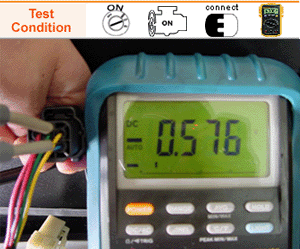
Start the engine
Measure voltage between the APS terminal 3 and the APS terminal 6 while idling.
For discriminating between old APS and new APS type connector configurations, Go to "Component Inspection" procedure
IS THERE approx. 0.2V ~ 0.5V ?
YES
Intermittent failure, system is O.K at this time.
Check for poor connections or losse wire at the APS and the ECM
Go to "Verification of Vehicle Repair" procedure
NO
Repair short in the wire between the APS terminal 3 and the ECM terminal 80/C230-1.
Repair short in the wire between the APS terminal 6 and the ECM terminal 79/C230-1.
Go to step 4
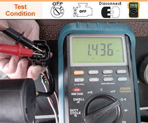
Stop the engine and without depressing the APS pedal, measure resistance between the APS terminal 3 and terminal 6 after disconnecting
IS THERE approx. 1.7 ㏀ ±0.8 ㏀ ?
YES
Recheck short in the wire between the APS terminal 3 and the ECM terminal 80/C230-1.
Recheck short in the wire between the APS terminal 6 and the ECM terminal 79/C230-1
NO
Replace the APS
For more detailed information, Go to "Component Inspection" procedure
YES
Go to "Verification of Vehicle Repair" procedure
In this DTC P0224 case, P1524/P01525(Sensor supply voltage 2 malfunction) and P0194 (Fuel pressure sensor )may be detected together.
Disconnect the APS and then turn the ignition switch ON. Measure the voltage between the APS terminal 1 and the APS terminal 6 after disconnection with the ignition switch ON
For discriminating between old APS and new APS type connector configurations, Go to "Component Inspection" procedure among the tree on the left-hand side of the window.
IS THERE approx. 5 V ?
YES
Intermittent failure, system is O.K at this time.
Check for poor connections or losse wire at the APS and the ECM.
Go to "Verification of Vehicle Repair" procedure
NO
Repair open or short in the wire between the APS terminal 1 and the ECM terminal 81/C230-1.
Repair open or short in the wire between the APS terminal 6 and the ECM terminal 79/C230-1.
Repair as necessary for wiring harness or connector terminal
Go to step 3
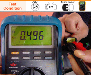
Check the voltage between the ECM terminal 81/C230-1 and the ECM terminal 79/C230-1 after turning the ignition switch ON.
IS THERE approx. 5V ?
YES
Recheck open or short in the wire between the APS terminal 1 and the ECM terminal 81/C230-1.
Recheck open or short in the wire between the APS terminal 6 and the ECM terminal 79/C230-1.
Go to "Verification of Vehicle Repair" procedure
NO
Go to "Verification of Vehicle Repair" procedure among the tree on the left-hand side of the window. Go to "Verification of Vehicle Repair" procedure