DTC | P0221 | Accelerator position sensor 2 circuit range / performance problem |
P0223 | Accelerator position sensor 2 circuit high input | |
P0224 | Accelerator position sensor 2 circuit intermittent |

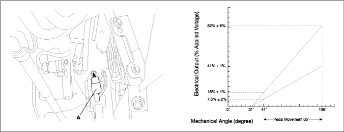
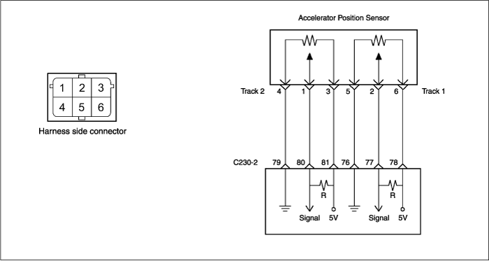
On electronic injection systems, there is no longer a load lever that mechanically controls the fuelling. The flow is calculated by the ECM depending on a number of parameters, including pedal position, which is measured using a potentiometer. The absence of a mechanical link between the accelerator pedal and the injection system presents a risk of loss of control of the engine in the event of a failure of the component in charge of providing the driver’s request information to the injection system. The pedal sensor(A) therefore has two potentiometers whose slides are mechanically solid. The two potentiometers are supplied from distinct and different power sources so there is built in redundancy of information giving reliable driver’s request information. A voltage is generated across the potentiometer in the acceleration position sensor as a function of the accelerator-pedal setting. Using a programmed characteristic curve, the pedal’s position is then calculated from this voltage.
DTC No | Detecting Condition & Limp Home | Suspect area |
P0221 P0223 P0224 | Detecting Condition P0221: When the signal of APS 2 is compared with that of APS 1, the error is detected. P0223: The signal voltage > 2.47V P0224: The supply voltage < 4.7V or > 5.1V - In this case, P1524/ P1525(Sensor Supply Voltage Malfunction) or P0194(Rail pressure sensor circuit intermittent) is detected together. Enable Condition Ignition swithc : ON Limp Home Fast idle speed at 950 RPM Air conditioning limitation by engine speed | - Open or short in APS track 2 circuit - APS - ECM |
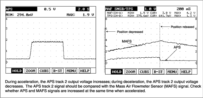
APS track 2 | Normal Parameter | |
Idle position (0%) | Fully open position (100 %) | |
Signal Voltage | 0.2 ~ 0.5V | 1.6 ~ 2.5V |


Proceed with ECM problem procedure. |