Enables steering around obstacles with a greater degree of certainty, even during emergency braking.
Enables stopping during emergency braking while keeping stability and steerability even on curves.
NORMAL BRAKING
Solenoid valve | State | Valve | Passage | Pump motor |
IN (NO) | OFF | OPEN | Master cylinder ⇔ Wheel cylinder | OFF |
OUT (NC) | OFF | CLOSE | Wheel cylinder ⇔ Reservoir |
Under the normal braking, voltage is not supplied to solenoid valve, inlet valve is opened and outlet valve is closed. When the brake is depressed, brake fluid is supplied to the wheel cylinder via solenoid valve to activate the brake. When the brake is released, brake fluid is back to the master cylinder via inlet valve and check valve. |
DUMP MODE
Solenoid valve | State | Valve | Passage | Pump motor |
IN (NO) | ON | CLOSE | Master cylinder ⇔ Wheel cylinder | ON |
OUT (NC) | ON | OPEN | Wheel cylinder ⇔ Reservoir |
Under the emergency braking, if the wheels start to lock up, HECU sends a signal to the solenoid valve to decrease the brake fluid, then voltage is supplied to each solenoid. At this time inlet valve is closed and brake fluid is blocked from the master cylinder. Conversely outlet valve is opened and brake fluid passes through wheel cylinder to reservoir, resulting in pressure decrease. |
HOLD MODE
Solenoid valve | State | Valve | Passage | Pump motor |
IN (NO) | ON | CLOSE | Master cylinder ⇔ Wheel cylinder | ON |
OUT (NC) | OFF | CLOSE | Wheel cylinder ⇔ Reservoir |
When the brake fluid pressure is maximally decreased in wheel cylinder, HECU sends a signal to solenoid valve to keep the fluid pressure, voltage is supplied to inlet valve but it is not supplied to outlet valve. At this time inlet and outlet valves are closed and brake fluid is kept in wheel cylinder. |
INCREASE MODE
Solenoid valve | State | Valve | Passage | Pump motor |
IN (NO) | OFF | OPEN | Master cylinder ⇔ Wheel cylinder | ON |
OUT (NC) | OFF | CLOSE | Wheel cylinder ⇔ Reservoir |
If HECU determines there's no lock-up in the wheel, HECU cuts voltage to solenoid valve. So voltage is not supplied to each solenoid valve, brake fluid passes through the inlet valve to wheel cylinder, resulting in pressure increase. |
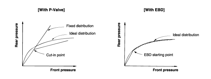
Function improvement of the base-brake system.
Compensation for the different friction coefficients.
Elimination of the proportioning valve.
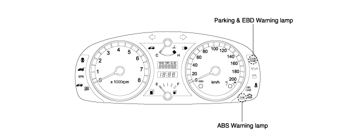
Failure recognition by the warning lamp.

FAIL CAUSE | SYSTEM | WARNING LAMP | ||
ABS | EBD | ABS | EBD | |
None | ON | ON | OFF | OFF |
Stop lamp switch failure | ON | ON | OFF | OFF |
One or two wheel speed sensor failure | OFF | ON | ON | OFF |
Pump malfunction | OFF | ON | ON | ON |
Low voltage | OFF | ON | ON | OFF |
3 or more wheel speed sensor failure Solenoid valve failure HECU malfunction Over voltage Valve relay failure Other failure | OFF | OFF | ON | ON |

ABS warning lamp module
The active ABS warning lamp module indicates the operating condition of the ABS.
The ABS warning lamp is turned on under the following conditions.
During the initialization phase after ignition switch ON. (3 seconds)
In the event of inhibition of ABS functions by failure.
When the system ECU is shut down even though ignition power is applied.
During diagnostic mode.
EBD warning lamp module
The active EBD warning lamp module indicates the operating condition of the EBD. However, in case the parking brake switch is turned on, the EBD warning lamp is always turned on regardless of EBD functions.
The EBD warning lamp is turned on under the following conditions.
During the initialization phase after ignition switch ON. (3 seconds)
In the event of inhibition of EBD functions by failure.
When the system ECU is shut down even though ignition power is applied.
When the parking brake switch is ON or brake fluid is low level.