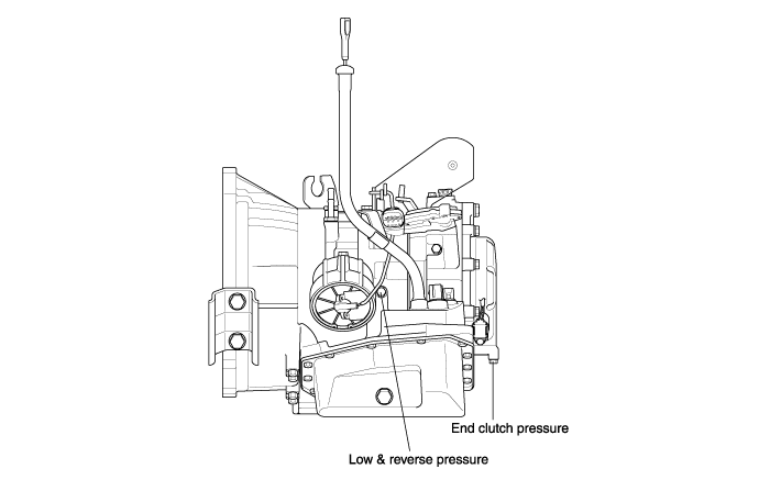
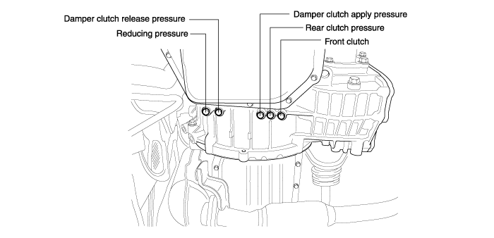
Attach the special oil-pressure gauge (09452-21500) and the adapter (09452-21002) to each oil-pressure outlet port.
When the reverse pressure is to be tested, the 3,000 kpa (400 psi) type of gauge should be used.
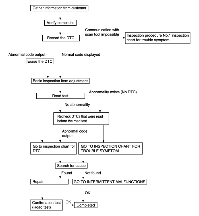
Procedure | Conditions | Operation | Judgement value | Inspection item | Inspection procedure if there is an abnormality |
1 | Ignition switch : ON Engine stopped | Overdrive switch ● ON ● OFF | ● OD ● OD-OFF | Overdrive switch | Overdrive switch system |
2 | Engine : Stopped | Starting test with lever in P or N range | Starting should be possible | Starting possible or impossible | Starting impossible (will not crank) |
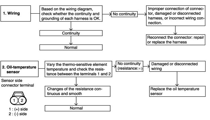
3 | Warming up | Drive for 15 minutes or more so that the automatic transmission fluid temperature 70~110°C | Gradually rises to 70~110°C | Oil temperature sensor | Codes - P0712, P0713 Oil temperature sensor system |
4 | Engine : Idling Selector lever : N | Accelerator pedal ● Fully closed ● Depressed ● Fully open (for at least 2 seconds) | ● 2~18% ● Gradually rises from (1) ● 80 ~ 100% | TPS | TPS system |
Selector lever operation ● N→D shift ● N→D shift | Should be no abnormal shifting shocks. Time lag should be within 2 seconds. | Malfunction when starting | Engine stalling during shifting | ||
Shocks when changing from N to D and long lag time | |||||
Shocks when changing from N to R and long lag time | |||||
Shocks when changing from N to D, N to R and long lag time | |||||
Engine : Idling (Vehicle stopped) Selector lever position : D | Selector lever operation ● N→D ● N→R shift | Should be no abnormal shifting shocks. Time lag should be within 2 seconds. | Driving impossible | Does not move forward | |
Does not move (forward or reverse) | |||||
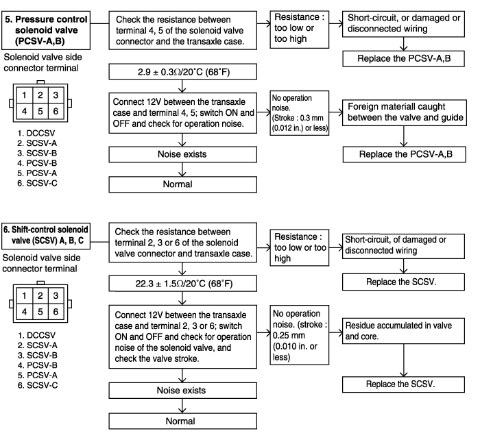
5 | Engine : Idling (Vehicle stopped) Selector lever position : D | Accelerator pedal ● Fully closed ● Depressed [Driving at 5km/h (3.1 mph)] | ● 75~90% ● 100% | Pressure control solenoid valve (PCSV) - A, B | Code P0745, P0775 - Pressure control solenoid valve system |
Accelerator pedal ● Fully closed ● Depressed | ● C ● 1 | Shift control solenoid valve A (SCSV-A) | Code P0750 - Shift control solenoid valve A system | ||
Code P0755 - Shift control solenoid valve B system | |||||
Code P0760 - Shift control solenoid valve C system | |||||
6 | Selector lever position : D Overdrive : OFF | Engine ● Idling (vehicle stopped) ● Driving at 10km/h ● Driving at constant speed of 50km/h (31mph) (20 seconds or more) ● Driving at constant speed of 40km/h (25mph) with selector lever in 2 range ● Driving at constant speed of 70km/h (43mph) with selector lever in D range | ● C ● 1 ● 3 ● 2 | Shift control solenoid valve A (SCSV-A) | Code P0750 - Shift control solenoid valve A system |
Shift control solenoid valve B (SCSV-B) | Code P0755 - Shift control solenoid valve B system | ||||
Shift control solenoid valve C (SCSV-C) | Code P0760 - Shift control solenoid valve C system | ||||
● OFF ● ON ● ON ● OFF | Kickdown servo switch | Code P1709 - Kickdown servo switch system | |||
● 0km/h ● 10km/h ● 50km/h ● 40km/h | Vehicle speed sensor | Vehicle speed sensor system | |||
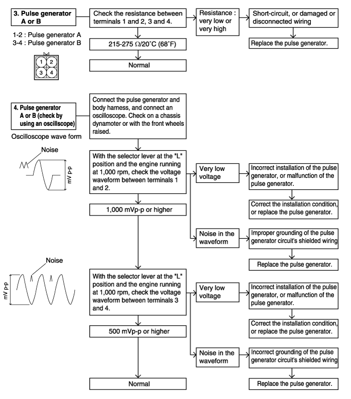
(3) 1,500~2,000rpm | Pulse generator A (PG-A) | Code P0717 - Pulse generator A system | |||
(3) 1,500~2,000rpm | Pulse generator B (PG-B) | Code P0722 - Pulse generator B system | |||
(3) 100~300rpm (5) 0~10rpm | Torque converter clutch solenoid | Code P0743 - Torque converter clutch solenoid | |||
(5) TCCS Duty : 40~85 | Torque converter clutch solenoid | Code P0743 - Torque converter clutch solenoid | |||
For (3) and (5), acceleration should be smooth with no abnormal vibration | Malfunction while driving | Poor acceleration | |||
Vibration | |||||
7 | Selector lever position : D Overdrive : ON | Engine (1) Driving at constant speed of 50km/h (31mph) (20 seconds or more) | (1) 3 speed gear (1) 1,500~2,000rpm | Shift control solenoid valve A (SCSV-A) | Code P0750 - Shift control solenoid valve A system |
Shift control solenoid valve B (SCSV-B) | Code P0755 - Shift control solenoid valve B system | ||||
Shift control solenoid valve C (SCSV-C) | Code P0760 - Shift control solenoid valve C system | ||||
Pulse generator A (PG-A) | Code P0717 - Pulse generator A system | ||||
Pulse generator B (PG-B) | Code P0722 - Pulse generator B system | ||||
8 | Selector lever position : D Overdrive : ON | ● Accelerate to 4th gear at TPS output of 1.5V (opening angle 30%) ● Slowly decelerate to a standstill ● Accelerate to 4th gear at TPS output of 2.5V (opening angle 50%) ● At 50km/h (31mph) in 4th gear, turn overdrive OFF ● At 50km/h (31mph) in 3rd gear, move selector lever to 2 range ● At 20km/h (12mph) in 2 range, move selector lever to L range. | For (1), (2) and (3) should match the specified output shaft speed (vehicle speed0, and there should be no abnormal shocks. For (4), (5) and (6), down shifting should be made immediately after operation. | Malfunction when shifting | Shocks and flare shifts |
Displaced shifting points | All points | ||||
Does not shift | No fail-safe codes | ||||
Code P0717 - Pulse generator A system | |||||
Code P0722 - Pulse generator B system | |||||
Code P0750 - Shift contorl solenoid valve A system | |||||
Code P0755 - Shift control solenoid valve B stystem | |||||
Code P0760 - Shift contorl solenoid valve C system | |||||
Code P0745, P0775 - Pressure control solenoid valve system | |||||
Code P0731 - 1st gear incorrect ratio | |||||
Code P0732 - 2nd gear incorrect ratio | |||||
Code P0733 - 3rd gear incorrect ratio | |||||
Code P0734 - 4th gear incorrect ratio |
DTC NO | Diagnosis items | Trouble area (Remedy) | MIL |
P0703 | Brake switch | ● Check the brake switch | X |
P0712 | Fluid temperature sensor -short circuit- | ● Fluid temperature sensor connector inspection ● Fluid temperature sensor inspection ● Fluid temperature sensor wiring harness inspection | O |
P0713 | Fluid temperature sensor -open circuit- | ||
P1709 | Kickdown servo switch -open circuit- | ● Check the kicdown servo switch connector ● Check the kicdown servo switch ● Check the kicdown servo switch wiring harness | X |
Kickdown servo switch -short circuit- | |||
P0717 | Pulse generator A -open circuit- | ● Check the pulse generator A and pulse generator B ● Check the vehicle speed reed switch (for chattering) ● Check the pulse generator A and B wiring harness | O |
P0722 | Pulse generator B -open circuit- | ||
P0750 | Shift control solenoid valve A | ● Check the solenoid valve connector ● Check the shift control solenoid valve A ● Check the shift control solenoid valve A wiring harness | O |
P0755 | Shift control solenoid valve B | ● Check the solenoid valve connector ● Check the shift control solenoid valve B ● Check the shift control solenoid valve A wiring harness | O |
P0760 | Shift control solenoid valve C | ● Check the solenoid valve connector ● Check the shift control solenoid valve C ● Check the shift control solenoid valve A wiring harness | O |
P0707 | Transaxle range switch -No signal- | ● Check the transaxle range switch connector and harness | O |
P0708 | Transaxle range switch -Multi signal- | ||
P0745 | Pressure control solenoid - A valve open circuit | ● Check the pressure control solenoid valve ● Check the pressure control solenoid valve wiring harness | O |
P0775 | Pressure control solenoid - B valve shor circuit | ||
P0743 | Damper clutch control solenoid | ● Inspection of solenoid valve connector ● Individual inspection of damper clutch control solenoid valve ● Check the damper clutch control solenoid valve wiring harness ● Check the PCM ● Inspection of damper clutch hydraulic system | X |
P0741 | Damper clutch -Stuck OFF- | ||
P0742 | Damper clutch -Stuck ON- | ||
P0731 | First gear system -Malfunction- | ● Check the pulse generator A and pulse generator B connector ● Check the one way clutch or rear clutch ● Check the pulse generator wiring harness | O |
P0732 | Second gear system -Malfunction- | ||
P0733 | Third gear system -Malfunction- | ● Check the rear clutch or control system ● Check the pulse generator A and pulse generator B connector ● Check the front clutch slippage or control system ● Check the pulse generator wiring harness ● Check the rear clutch slippage or control system | O |
P0734 | Fourth gear system -Malfunction- | ● Check the pulse generator A and pulse generator B connector ● Kickdown brake slippage ● Check the end clutch or control system ● Check the pulse generator wiring harness | O |
DTC NO | Description | Fail-safe | Note (Relation to diagnostic trouble code) |
P0717 | Open-circuited pulse generator A | Locked in third (D) or second (2, L) gear | When code P0717 is generated fourth time |
P0722 | Open-circuited pulse generator B | Locked in third (D) or second (2,L) gear | When code P0722 is generated fourth time |
P0750 | Open-circuited or shorted shift control solenoid valve A | Lock in third gear | When code P0750 is generated fourth time |
P0755 | Open-circuited or shorted shift control solenoid valve B | Lock in third gear | When code P0755 is generated fourth time |
P0760 | Open-circuited or shorted shift control solenoid valve C | Lock in third gear | When code P0760 is generated fourth time |
P0745 P0775 | Open-circuited shorted pressure control solenoid valve | Lock in third (D) or second (2,L) | When codes P0745 or P0775 are generated fourth time |
P0731 P0732 P0733 P0734 | Gear shifting does not match the engine speed | Lock in third (D) or second (2,L) | When either codes P0731, P0732, P0733 or P0734 are generated fourth time |
Trouble symptom | Inspection procedure No. | Reference page | |
Communication with scan tool is not possible | 1 | ||
Driving impossible | Starting impossible (will not crank) | 2 | |
Does not move forward | 3 | ||
Does not back-up | 4 | ||
Does not move (forward or reverse) | 5 | ||
Malfunction when starting | Engine stalling during shifting | 6 | |
Shocks when shifting from N to D and long lag time | 7 | ||
Shocks when shifting from N to R and long lag time | 8 | ||
Shocks when shifting from N to D, N to R and long lag | 9 | ||
Malfunction when shifting | Shocks when shifting from N to R and long lag time | 10 | |
Early, late shift points | Shocks when shifting from N to D, N to R and long lag | 11 | |
Shocks and flare shift | 12 | ||
Does not shift | All points | 13 | |
Malfunction while driving | Some points (poor acceleration) | 14 | |
Vibration | 15 | ||
Overdrive switch system | 16 | ||
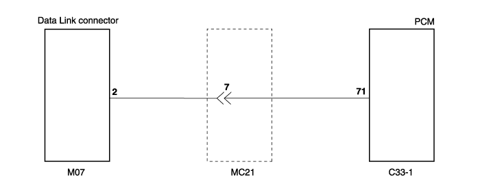
Communication with scan tool is not possible | Possible cause |
If communiction with the scan tool is not possible, the cause may be a defective diagnosis line or PCM is not functioning | ● Malfunction of diagnosis line ● Malfunction of PCM power ● Malfunction of PCM ground circuit ● Malfunction of PCM |

Starting Impossible (will not crank) | Possible cause |
Starting is not possible when the selector lever is in P or N range. In such cases, the cause may be a defective engine system, torque converter or oil pump. | ● Malfunction of the engine system ● Malfunction of the oil pump ● Malfunction of the torque converter |
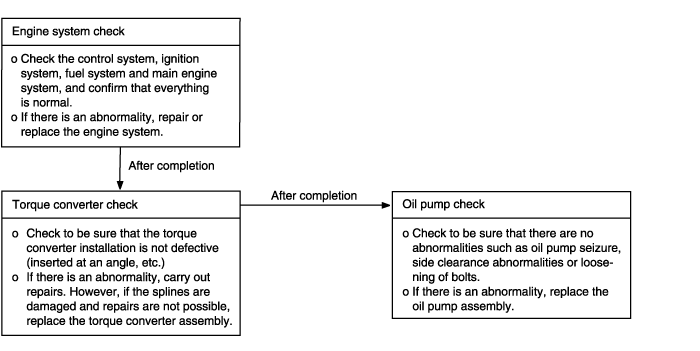
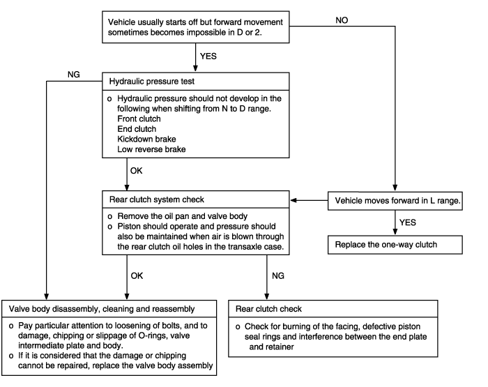
Does not move forward | Possible cause |
When the engine is idling, the vehicle does not move forward even if the selector lever is shifted from N to D, 2 or L range. In such cases, the cause may be abnormal line pressure, or a defective rear clutch or one-way clutch. | ● Abnormal line pressure ● Malfunction of rear clutch ● Malfunction of one-way clutch ● Malfunction of valve body |
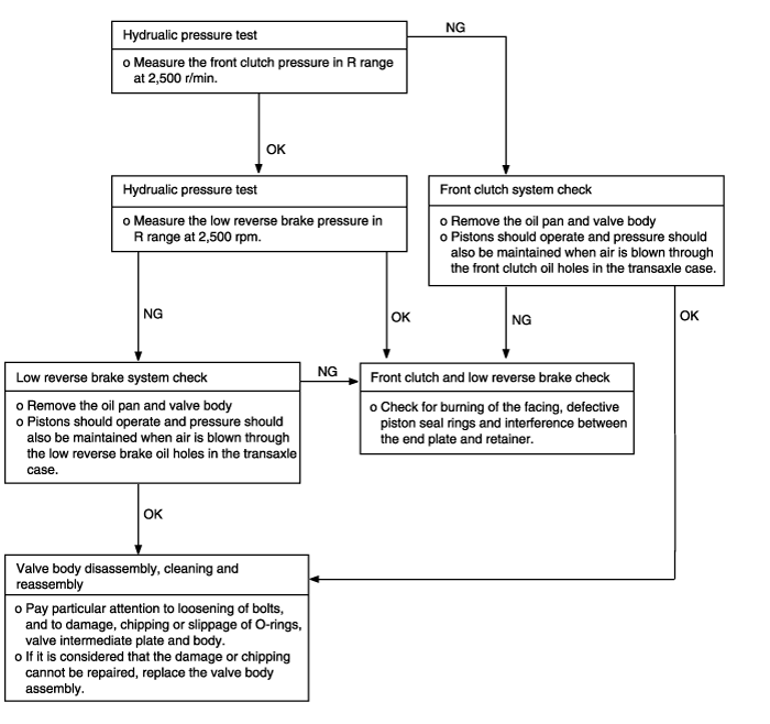
Does not move back-up | Possible cause |
When the engine is idling, the vehicle does not back-up even if the selector lever is shifted from N to R range. In such cases, the cause may be abnormal pressure in the low reverse brake or front clutch, or a defective low reverse brake or front clutch. | ● Abnormal low reverse brake pressure ● Abnormal front clutch pressure ● Malfunction of front clutch ● Malfunction of low reverse brake ● Malfunction of valve body |
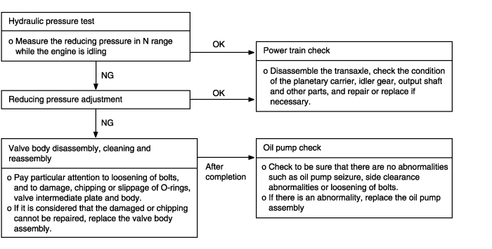
Does not move (forward or reverse) | Possible cause |
When the engine is idling, the vehicle does not move forward or reverse even if the selector lever is shifted from N to D, 2, L or R range. In such cases, the cause may be abnormal reducing pressure, or a defective oil pump or power train. | ● Abnormal reducing pressure ● Malfunction of power train ● Malfunctin of oil pump ● Malfunction of valve body |
Engine stalling during shifting | Possible cause |
When the engine is idling, the engine stalls when the selector lever is shifted from N to D, 2, L or R range. In such cases, the cause may be a defective engine system or damper clutch control solenoid valve. | ● Malfunction of engine system ● Malfunction of torque converter clutch solenoid ● Malfunction of valve body ● Malfunction of torque converter |
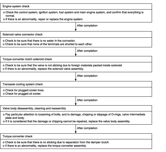
Shocks when shifting from N to D and long lag time | Possible cause |
When the engine is idling, abnormal shocks or a lag time of 2 seconds or more occur when the selector lever is shifted from N to D range. In such case, the cause may be a defective rear clutch or valve body. | ● Malfunction of rear clutch ● Malfunction of valve body ● Malfunction of closed throttle position switch |
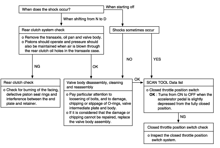
Shocks when shifting from N to R and long lag time | Possible cause |
When the engine is idling, abnormal shocks or a lag time of 2 seconds or more occurs when the selector lever is shifted from N to R range. In such cases, the cause may be abnormal low reverse brake or front clutch pressure, or a defective low reverse brake or front clutch. | ● Abnormal front clutch pressure ● Abnormal low reverse brake pressure ● Malfunction of front clutch ● Malfunction of low reverse brake ● Malfuntion of valve body |
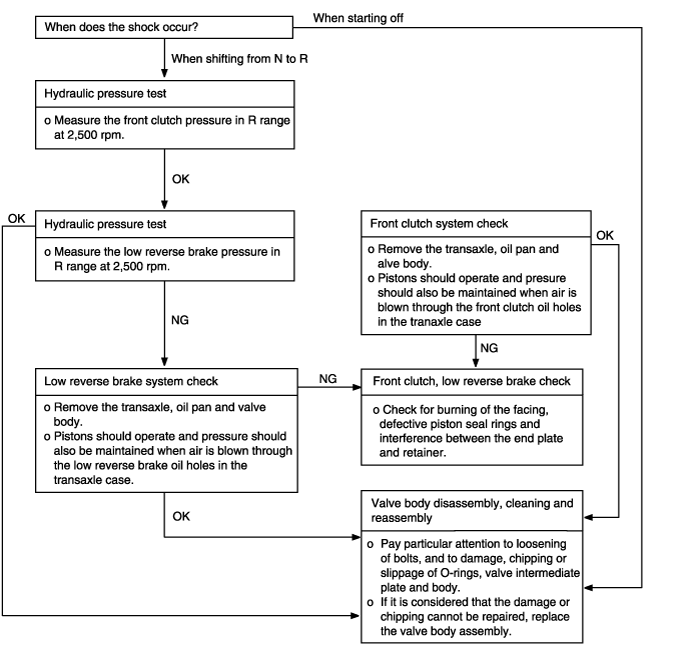
Shocks when shifting from N to D,N to R and long lag time | Possible cause |
When the engine is idling, abnormal shocks or a lag time of 2 seconds or more occur when the selector lever is shifted from N to D range and from N to R range. In such cases, the cause may be abnormal reducing pressure or a defective oil pump. | ● Abnormal reducing pressure ● Malfunction of oil pump ● Malfunction of valve body |
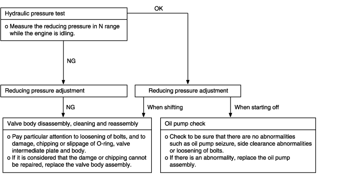
Shocks and flare shifts | Probable cause |
Shocks occur when driving due to upshifting or downshifting. In addition,the engine speed during shifting increases abnormally in comparison to normal shifting. In such cases, the cause is probably abnormal reducing pressure or a defective kickdown servo switch. | ● Malfunction of kickdown servo switch ● Abnormal reducing pressure ● Malfunction of valve body ● Malfunction of closed throttle position switch ● Malfunction of pressure control solenoid valve ● Malfunction of clutches and brakes |
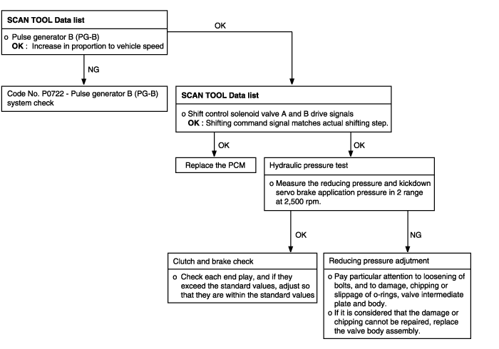
All points (Early, late shifting points) | Possible cause |
All shift points occurs early, late while driving. In such cases, the cause may be a defective pulse generator B (PG-B) or shift control solenoid valve A or B (SCSV-A, B). | ● Malfunction of pulse generator B (PG-B) ● Malfunction of shift control solenoid valve A or B (SCSV-A, B) ● Malfunction of PCM ● Abnormal reducing pressure or kickdown servo brake application pressure ● Malfunction of clutches and brake |
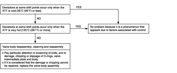
Some points (Early, late shifting points) | Possible cause |
Some shift points occurs early, late while driving. In such cases, the causemay be a defective valve body, or it is phenomenon related to control and is not an abnormality. | ● Malfunction of valve body |
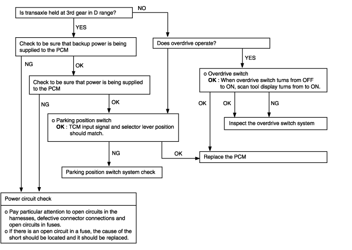
Does not shift | Possible cause |
Shifting does not occur while driving, and no fail-safe codes are output.In such cases, the cause may be a defective overdrive switch or parking switch. | ● Malfunction of overdrive switch ● Malfunction of parking position switch ● Malfunction of power supply circuit ● Malfunction of PCM |
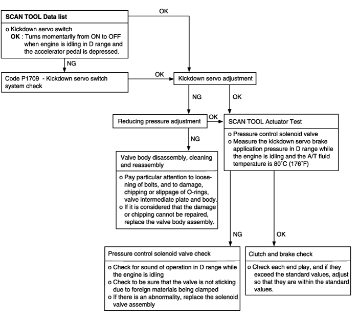
Poor acceleration | Possible cause |
While driving, acceleration is poor even if downshifting is performed. In such cases, the cause may be a defective clutch or brake, or a defective engine system. | ● Malfunction of clutch and brakes ● Malfunction of engine system |
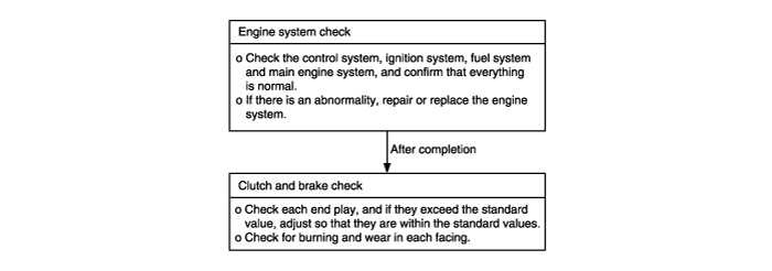
Vibration | Possible cause |
Vibration occurs when driving at constant speed or when accelerating in top range. In such case, the cause may be abnormal torque converter clutch pressure or a defective torque converter. | ● Abnormal torque converter clutch pressure ● Malfunction of engine system ● Malfunction of torque converter ● Malfunction of valve body |
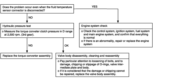
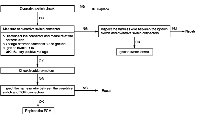
Overdrive switch system | Possible cause |
In cases such as the above, the cause may be a defective overdrive switch circuit or defective ignition switch circuit. | ● Malfunction of overdrive switch ● Malfunction of connector ● Malfunction of ignition switch ● Malfunction of PCM |
Turn the ignition switch OFF.
Connect the Hi-Scan Pro to the data link connector.
Turn the ignition switch ON.
Use the Hi-Scan Pro to check the diagnostic trouble code.
Repair the faulty part from the diagnosis chart.
Erase the diagnostic trouble code.
Disconnect the Hi-Scan Pro.
An on-board diagnostic light comes on to notify the driver that there is problems in the vehicle. However, when an irregular state returns to normal, the malfunction indicator light will go out automatically after 3 driving cycles that have no same fault. Immediately after the ignition switch is turned on, the malfunction indicator light operates normally. (See FL-section)
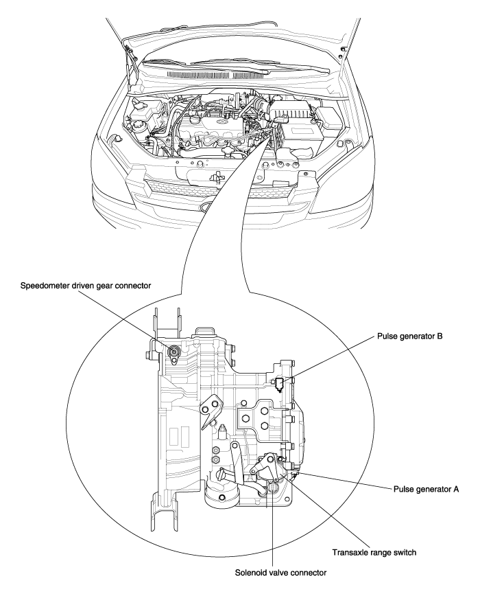
Fluid temperature sensor
Pulse generator A (PG-A)
Pulse generator B (PG-B)
Shift control solenoid valve A (SCSV-A)
Shift control solenoid valve B (SCSV-B)
Shift control solenoid valve C (SCSV-C)
Pressure control solenoid valve (PCSV-A)
Pressure control solenoid valve B (PCSV-B)
Damper clutch solenoid valve (DCCSV)
Shift stage synchronize
Transaxle range switch
Diagnosis items | Checking procedures | Checking items (Remedy) | |
Check conditions | Normal value | ||
Throttle position sensor (TPS) | Accelerator pedal fully released | 2 ~ 18 % | ● TPS or circuit harness if no change occurs ● TPS or accelerator pedal cable if gradual change is not noted |
Press accelerator pedal slowly | Varies with accelerator opening | ||
Accelerator pedal pressed to floor | 80 ~ 100% | ||
Fluid temperature sensor | Cold engine (before starting) | Equivalent to outside air temperature | ● Fluid temperature sensor or circuit harness |
While warming up engine | Gradual increase | ||
After warming up engine | 70 ~ 110°C | ||
Kickdown servo switch | L range : Idling | ON | ● Kickdown servo misadjusted ● Kickdown servo switch or circuit harness ● Kickdown servo |
D range : First or third gear | ON | ||
D range : Second or fourth gear | OFF | ||
Engine speed | P range : Idling Accelerator pedal : Fully closed | 600 ~ 800rpm | ● Ignition system ● Ignition signal pick-up circuit harness |
P range : Idling Accelerator pedal : depressed | |||
Air conditioning relay signals | P range : Idle, air conditioning ON | ON | ● Air conditioning power relay circuit harness |
P range : Idle, air conditioning OFF | OFF | ||
Shift position | 1st speed : 10km/h | First | ● PCM ● Transaxle range switch system ● TPS system |
2nd speed : 30km/h | Second | ||
3rd speed : 50km/h | Third | ||
4th speed : 80km/h | Fourth | ||
Pulse generator A | D range (OD OFF) : driving at 50 km/h (31 mph) in third gear | 1,500 ~ 2,000rpm | ● Pulse generator A or circuit harness ● Pulse generator A shielded wire ● Incoming noise from outside |
D range (OD ON) : driving at 80 km/h (50 mph) in fourth gear | 1,700 ~ 2,000rpm | ||
Pulse generator B | D range (OD OFF) : driving at 50 km/h (31 mph) in third gear | 1,500 ~ 2,000rpm | ● Pulse generator B or circuit harness ● Pulse generator B shielded wire ● Incoming noise from outside |
D range (OD ON) : driving at 80 km/h (50 mph) in fourth gear | 1,500 ~ 2,000rpm | ||
Overdrive switch | ● Ignition switch : ON ● Engine : stopped ● Overdrive switch is turned ON | OD-ON | ● Overdrive switch or circuit harness |
● Ignition switch : ON ● Engine : stopped ● Overdrive switch is turned OFF | OD-OFF | ||
Transaxle range switch | Shift selector lever to P range | P | ● Transaxle range switch misadjusted ● Transaxle range switch or circuit harness ● Manual control cable ● If selector lever is inoperative, check shift lock mechanism |
Shift selector lever to R range | R | ||
Shift selector lever to N range | N | ||
Shift selector lever to D range | D | ||
Shift selector lever to 2 range | 2 | ||
Shift selector lever to L range | L | ||
Vehicle speed sensor | Keep vehicle stopped | 0km/h | ● Vehicle speed sensor if high speed signal is delivered while vehicle is stopping ● In other cases, vehicle speed sensor or circuit harness |
Driving at 40 km/h (25 mph) in 2 range | 40km/h (25 mph) | ||
Driving at 50 km/h (31 mph) in D range, OD OFF | 50km/h (31 mph) | ||
PCSV-A duty | D range : Idling | 75 ~ 90% | ● When accelerator pedal is slightly pressed while idling in D range, duty should become 100% ● PCM ● TPS system |
D range : first gear | 100% | ||
PCSV-B duty | D range : Idling | 0% | ● PCM ● TPS system |
D range : first gear | 0% | ||
Torque converter slip amount | D range : third gear, 70km/h, OD OFF | 0~50rpm | ● Torque converter ● Ignition signal wire or pulse generator A system ● Inappropriate transaxle fluid pressure ● Torque converter control solenoid valve |
DCCSV duty | D range : third gear, 70km/h, OD OFF | 40 ~ 85% | ● PCM ● TPS system ● Pulse generator A system ● Torque converter control solenoid valve |
Select or lever position | Overdrive control switch | Shifting gear | Engine start | Parking Mechanism | Clutch | Brake | ||||
C1 | C2 | C3 | OWC | B1 | B2 | |||||
P | - | Neutral | Possible | O | ||||||
R | - | Reverse | O | O | ||||||
N | - | Neutral | Possible | |||||||
D | ON | First | O | O | ||||||
Second | O | O | ||||||||
Third | O | O | O | |||||||
Fourth | O | O | ||||||||
D | OFF | First | O | O | ||||||
Second | O | O | ||||||||
Third | O | O | O | |||||||
2 | - | First | O | O | ||||||
Second | O | O | ||||||||
L | - | First | O | O | ||||||
C1 : Front clutch
C2 : Rear clutch
C3 : End clutch
OWC : One way clutch
B1 : Kickdown brake
B2 : Low&reverse brake
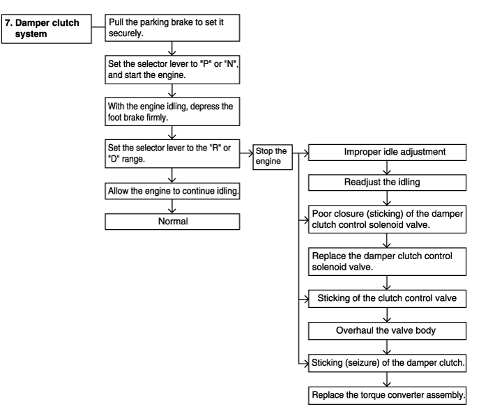
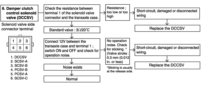
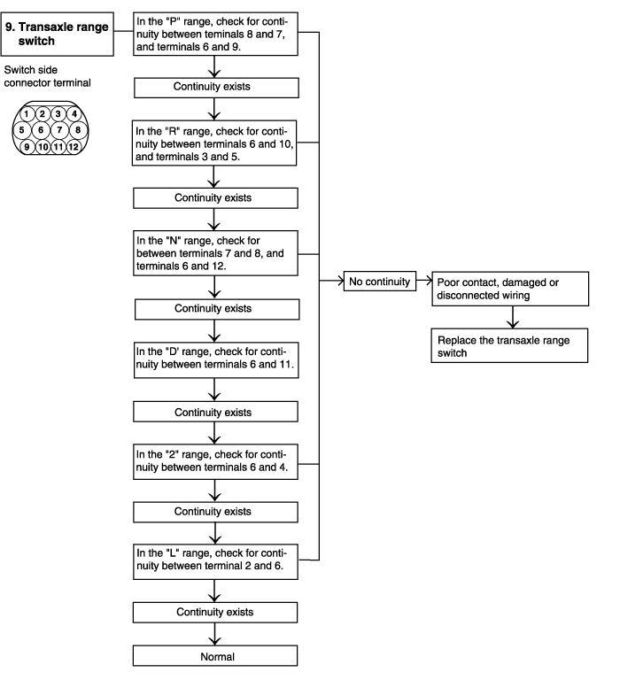
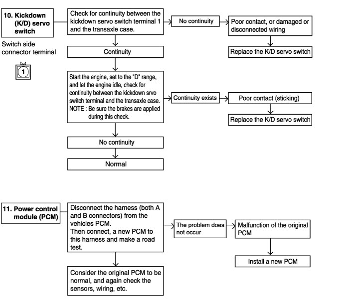
Completely warm up the transaxle.
Raise the front of the vehicle so that the front wheels can be rotated.
Connect an engine tachometer and place it in a position where it's easy to see.
Attach the special oil-pressure gauge (09452-21500) and the adapter (09452-21002) to each oil-pressure outlet port.
When the reverse pressure is to be tested, the 3,000 kpa (400 psi) type of gauge should be used.

Measure the oil pressure under various conditions. check to be sure that the measured results are within the standard value range shown in the "Standard oil pressure table" below. If the oil pressure is not within the specified range, check and repair as described in the section "Preliminary Steps if Oil Pressure Is Not Normal" on the next page.
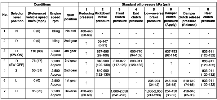
Must be 19.6 kPa (2.8 psi) or less.
Trouble symptom | Probable cause | Remedy |
Line pressures are all low (or high). Line pressure refers to oil pressures 2, 3, 4, 5, 6, 7 and 8 in the "Standard oi; pressure table" on the previous page. | ● Obstructed oil filter ● Improper adjustment of oil pressure (line pressure) regulator valve ● Sticking of regulator valve ● Looseness of valve body tightening part ● Improper oil pump discharge pressure | ● Visually inspect the oil filter; replace the oil filter if it is restricted. ● Measure line pressure 2 (kickdown brake pressure); if the pressure is notthe standard value, readjust the line pressure, or if necessary, replace thevalve body assembly. ● Check the operation of the regulator valve; repair if necessary, or replacethe valve body assembly. ● Tighten the valve body tightening bolt and installation bolt. ● Check the side clearance of the oil pump gear; replace the oil pump assembly if necessary. |
Improper reducing pressure | ● Improper line pressure ● Clogging of the filter (L-shaped type) of the reducing-pressure circuit ● Improper adjustment of the reducing pressure ● Improper adjustment of the reducing pressure ● Sticking of the reducing valve ● Looseness of valve body tightening part | ● Check the 2 kickdown brake pressure (line pressure); if the line pressure is not the standard value, check as described in item 1 above. ● Disassemble the valve body assembly and check the filter; replace the filter if it is restricted. ● Measure the 1 reducing pressure; if it is not the standard value, readjust, or replace the valve body assembly. ● Check the operation of the reducing valve; if necessary, repair it, or replace the valve body assembly. ● Tighten the valve body tightening bolt and installation bolt. |
Improper kickdown brake pressure | ● Malfunction of the D ring or seal ring or the sleeve or kickdown servo piston. ● Looseness of valve body tightening part. ● Functional malfunction of the valve body assembly. | ● Disassemble the kickdown servo and check whether the seal ring or D-ring is damaged. If it is cut or has scratches, replace the seal ring or D-ring. ● Tighten the valve body tightening bolt and installation bolt. ● Replace the valve body assembly. |
Improper front clutch pressure | ● Malfunction of the D-ring of the sleeve or kickdown servo piston. ● Looseness of valve body tightening part ● Malfunction of the valve body assembly. ● Wear of the front clutch piston or retainer, or malfunction of the D-ring. (Refer to the figure on the next page.) ● Oil pump gasket or seal ring (2) damaged. | ● Disassemble the kickdown servo and check whether the seal ring is damaged.If it is cut or has scratches, replace the seal ring or D-ring. ● Tighten the valve body tightening bolt and installation bolt. ● Replace the valve body assembly. ● Disassemble the transaxle itself and check whether or not there is wear of the front clutch piston and retainer inner circumference, or damage of the D-ring. If there is any wear or damage, replace the piston, retainer, D-ring and or seal ring. |
Improper end clutch pressure | ● Malfunction of a D-ring, seal ring of the end clutch or O-ring of the pipe (Refer to the figure on the next page.) ● Looseness of valve body tightening part. ● Malfunction of the valve body assembly | ● Disassemble the end clutch and check the seal ring, D-ring of the piston, seal ring of the retainer, etc.; replace if there are cuts, scars, scratcher or damage. ● Tighten the valve body tightening bolt and installation bolt. ● Replace the valve body assembly. |
Improper low-reverse brake pressure | ● O-ring between valve body and transaxle damaged or missing ● Looseness of valve body tightening part ● Malfunction of the valve body assembly ● Malfunction of the O-ring of the low-reverse brake piston or the O-ring of the retainer (Refer to the figure on the next page.) | ● Remove the valve body assembly and check to be sure that the O-ring at the upper surface of the upper valve body is not missing or damaged; install or replace the O-ring if necessary. ● Tighten the valve body tightening bolt and installation bolt. ● Replace the valve body assembly. ● Disassemble the transaxle itself and check the O-ring for damage; replace if there are cuts, scars, scratches or damage. |
Improper torque converter pressure | ● Sticking of the damper clutch control solenoid valve (DCCSV) ● Clogging or leaking of the oil cooler and/or lines. ● Damaged seal ring of the input shaft. ● Malfunction of the torque converter. | ● Check the operation of the damper clutch system and the DCCSV. ● Repair or replace, as necessary, the cooler and/or lines. ● Disassemble the transaxle itself and check for damage of the seal ring; replace the seal ring if there is damage. ● Replace the torque converter. |
Improper rear clutch pressure | ● Malfunction of the D-ring or seal ring of the rear clutch. ● Looseness of valve body tightening part. ● Functional malfunction of the valve body assembly. | ● Tighten the value body tightening bolt and installation bolt. ● Replace the valve body assembly. |
Improper damper clutch release pressure. | Same as the probable cause of damper clutch release pressure | Same as the remedy of damper clutch release pressure. |
A stall test determines the maximum engine speed obtained at full throttle in "D" and "R" range. This test checks the torque converter stator overrunning clutch operation, and the holding ability of the transaxle clutches and the low-reverse brake.
During this test, make sure that nobody stands in front of or behind the vehicle.
Check transaxle fluid level. Fluid should be at normal operating temperature [80~90°C (176~194°F)]. Engine coolant should also be at normal operating temperature [80~90°C (176~194°F)].
Apply chocks to both rear wheels.
Attach an engine tachometer.
Apply the parking and service brakes fully.
Start the engine.
With the selector lever in the "D" position, depress the accelerator pedal fully to read maximum engine rpm. Do not hold the throttle wide open any longer than is necessary to obtain maximum engine rpm reading, and never longer than 5 seconds at a time. If more than one stall test is required, operate the engine at approximately 1,000 rpm in neutral for 2 minutes to cool the transaxle fluid between tests.
Stall speed : 2,200~2,800rpm
Place the selector lever in the "R" position and perform the stall test by the same procedure as previously described.
If stall speed is higher than specification, the rear clutch or overrunning clutch of the transaxle is slipping. In this case, perform a hydraulic test to locate the cause of slippage.
If the stall speed is higher than specification, the front clutch of the transaxle or low-reverse brake is slipping. In this case, perform a hydraulic test to locate the cause of slippage.
If the stall speed is lower than specification, insufficient engine output or a faulty torque converter is suspected. Check for engine misfiring, improper ignition timing, or valve clearance etc. If these are good, the torque converter is faulty.
Drive the vehicle until the fluid reaches normal operating temperature [80~90°C (176~194°F)].
Place the vehicle on a level surface.
Move the selector lever through all gear position. This will fill the torque converter and hydraulic system with fluid, then place lever in "N" (Neutral) position.
Before removing the dipstick, wipe all contaminants from around the dipstick. Then take out the dipstick and check the condition of the fluid. The transaxle should be overhauled under the following conditions.
If there is a "burning" door.
If the fluid color has become noticeably blacker.
If there is a noticeably excessive amount of metal particles in the fluid.
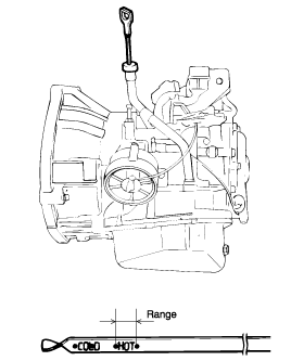
Check to see if the fluid level is in the "HOT" range on dipstick. If fluid level is low, add automatic transaxle fluid until the level reaches the "HOT" range.
Transaxle fluid : GENUINE DIAMOND ATF SP-III
Low fluid level can cause a variety of abnormal conditions because it allows the pump to take in air along with fluid. Air trapped in the hydraulic system forms bubbles which are compressable. Therefore, pressures will be erratic, causing delayed shifting, sliping clutches and brakes, etc. Improper filling can also raise fluid level too high. When the transaxle has too much fluid, gears churn up foam and cause the same conditions which occur with low fluid level, resulting in accelerated deterioration of automatic transaxle fluid. In either case, air bubbles can cause overheating, and fluid oxidation, which can interfere with normal valve, clutch, and servo operation. Foaming can also result in fluid escaping from the transaxle vent where it may be mistaken for a leak.
Be sure to examine the fluid on the dipstick closely.
Shift the selector lever to each range and check to see that the lever moves smoothly and is controlled. Check to see that the position indicator is correct.
Check to be sure that the selector lever can be shifted to each position.
Start the engine and check to see if the vehicle moves forward when the selector lever is shifted from "N" to "D" and moves backward when shifted to "R".
When the shift lever malfunctions, adjust the control cable and the selector lever sleeve. Check for worn shift lever assembly sliding parts.
Place selector lever in "N" (Neutral) position.
Loosen the manual control lever lock nut to seperate the cable and lever.
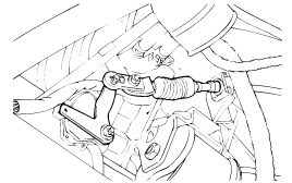
Place the manual control lever in the "N" (Neutral) position.
Turn the transaxle range switch body until the 12 mm (0.47 in.) wide end of the manual control lever aligns with the switch body flange [12 mm (0.472 in.) wide portion].
Tighten the attaching bolts (2 pcs.) to the specified torque.
Transaxle Range Switch Attaching Bolt :
10~12 Nm (100~120 kg·cm, 7~9 lb·ft)
When setting up the switch body, be careful that the O-ring does not drop from the switch body. Tighten the attaching bolts carefully.
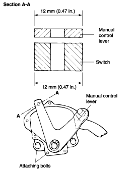
Make sure that the selector lever is in the "N" (Neutral) position.
Adjust the flange nut so that there is no slack in the control cable and make sure that the selector lever operates smoothly.
Run the vehicle and confirm that the transaxle is set in each range when the selector lever is shifted to each position.
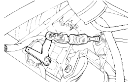
Completely remove all dirt and other contaminating materials adhered around the kickdown adjust screw.
Loosen the lock nut.
Loosen and tighten the adjust screw two times by torque of 5 Nm (3.6 lb·ft)
Tighten adjust screw by torque of 5 Nm and then, loosen the adjust screw 3 to 3-1/3 turns.
Tighten the lock nut to the specified torque.
Lock nut : 15~22 Nm (150~220 kg·cm, 11~16 lb·ft)
Before assembling, apply sealant (DC780) to the center portion of the adjust screw.
Drain out the automatic transaxle fluid.
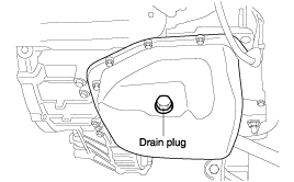
Remove the oil pan.
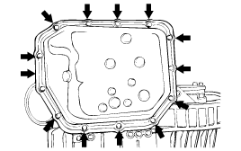
Remove the oil filter.
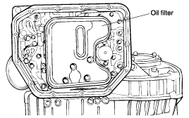
Remove the oil-temperature sensor.
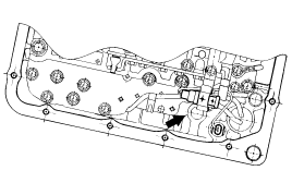
Press the tab of the solenoid valve harness grommet and push in.
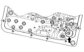
Remove the valve body assembly. The manual valve can come out, so be careful not to drop it.
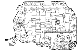
Turn the adjustment screw of the regulator valve and adjust so that the line pressure (kickdown brake pressure) reaches the standard value. When the adjustment screw is turned clockwise, the line pressure becomes lower; when it is turned counter-clockwise, it becomes higher.
Standard value :
860~900 kPa (122~129 psi, 8.77~9.18 kg/cm²)
Oil pressure change for each turn of adjustment screw :
38 kPa (5.4 psi, 0.39 kg/cm²)
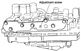
Check to be sure that the O-ring is installed on the upper surface of the valve body at the place.
Replace the O-ring of the solenoid valve connector with a new one.
Install the valve body assembly to the case and then insert the solenoid valve connector into the case. Be sure, at this time, that the notched part of the connector faces as shown in the figure. Also be careful that the lead wiring isn't caught.

Tighten the valve body assembly mounting bolts to 10-12 Nm (100-120 kg·cm, 7-9 lb·ft).
Install the oil filter.

Install a new oil pan gasket with the oil pan.
Pour in the specified amount of automatic transaxle fluid.
Perform the oil pressure test. Readjust if necessary.
If the Scan Tool is not abailable
Remove parts up to the oil filter in the same way as for adjustment of the line pressure. The valve body need not be removed.
Turn the adjustment screw of the lower valve body and adjust so that the reducing pressure is the standard value. When the adjustment screw is turned clockwise, the reducing pressure becomes lower; when it is turned counter clockwise, it becomes higher.
When adjusting the reducing pressure, aim for the center value (425 kPa, 60 psi) of the standard value allowance.
Standard value :
420 kPa (60 psi, 4.2±0.2 kg·cm)
Oil pressure change for each turn of the adjustment screw :
22 kPa (4.3 psi, 0.22 kg·cm²)
Install the oil filter and oil pan in the same way as for adjustment of the line pressure.
Peform the oil pressure test. Readjust if necessary.
If the Scan Tool is used
Adjust the pressure control solenoid so that the kickdown brake pressure is the standard value when activated to 50% duty by the Scan Tool.
Standard value :
320±30 kPa (39±1 psi, 3.2±0.3 kg·cm²)
Oil pressure change for each turn of the adjustment screw :
30 kPa (3 psi, 0.3 kg·cm²)
Check to be sure that the reducing pressure (after the adjustment is completed) is within the range of 370~490 kPa (53~70 psi, 3.8~5.0 kg·cm²).
This adjustment should be made with an oil temperature of 80-90°C (176-194°F). If the adjustment is made at a temperature that is too high, the line pressure will drop during idling, with the result that it might not be possible to make the correct adjustment.
Refer to GROUP FUEL SYSTEM.
Disconnect the drive shaft from the transaxle. (Refer to DRIVE SHAFT&FRONT AXLE)
Using a flat-tip (-) screwdriver, remove the oil seal.
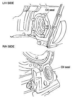
Using the special tool (09431-21200), tap the drive shaft oil seal into the transaxle.
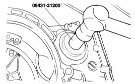
Apply a coating of the transaxle fluid to the lip of the oil seal.
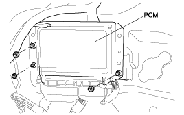
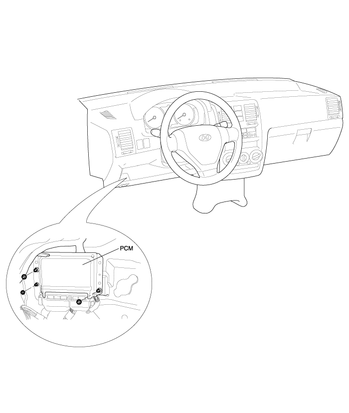
PCM (Power Control Module) is located at the dash panel of the upper side of brake pedal in the driver side.
