Drain the clutch fluid through the bleed plug (A).
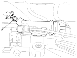
Drain the clutch fluid through the bleed plug (A).

Remove clevis pin (A), cotter pin (C) and washer (B).
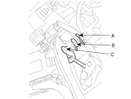
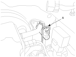
Disconnect the clutch tube (A) (Master cylinder side)
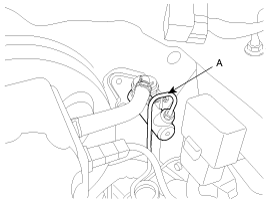
Remove the flexible hose(A) connected to brake reserve tank.
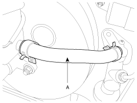
Remove the master cylinder mounting nuts(A) under the instrument panel and also remove the support nut in the engine room if necessary.
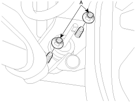
Install the master cylinder (A).
TORQUE :
9-14 Nm (90-140 kgf.cm, 7-10 Ib-ft)

Connect the flexible hose(A) of the brake reserve tank to the master cylinder.

Install the push rod(A) to the clutch pedal.
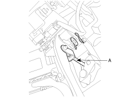
Apply the specified grease to the clevis pin and washer.
Wheel bearing grease: SAE J310, NLGI NO. 2
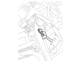
Pour the clutch fluid into the clutch master cylinder.
Connect the clutch tube(A) to the master cylinder.
TORQUE :
13-17 Nm (130-170 kgf.cm, 10-13 Ib-ft)
Bleed the clutch system.
Remove the piston stop ring.
Pull out the push rod and piston assembly.
Remove the reserve tank band, reserve tank cap, and reserve tank.
Use care not to damage the master cylinder body and piston assembly.
Do not disassemble the piston assembly.
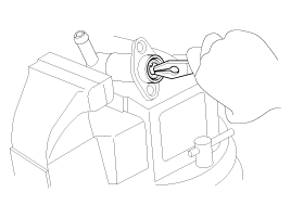
Check the inside of the cylinder body for rust, pitting or scoring.
Check the piston cup for wear or distortion.
Check the piston for rust, pitting or scoring.
Check to make sure the clutch line tube is not clogged or restricted in any way.
Measure the master cylinder inside diameter and the piston outside diameter with a cylinder gauge micrometer.
Measure the inside diameter of the master cylinder at three places (bottom, middle, and top) in a perpendicular direction.
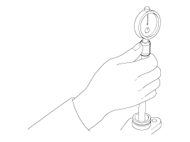
If the master cylinder-to-piston clearance exceeds the limit, replace the master cylinder and/or piston assembly.
Limit : 0.15 mm (0.006 in)
Apply the specified fluid to the inner surface of the master cylinder body (A) and to the entire periphery of the piston assembly (B).
Specified fluid: Brake fluid DOT 3 or DOT 4
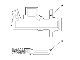
Install the piston assembly.
Install the piston snap ring.
Install the push rod assembly.