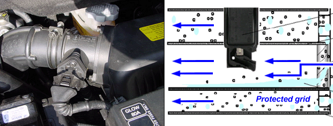

The mass air flow sensor (MAFS) has an intake air temperature sensor built-in and is located between the air cleaner assembly and the throttle device. The MAFS uses a hot film type sensing-element to measure the mass of intake air entering the engine. And send the signal to ECM. A large amount of intake air represents acceleration or high load conditions while a small amount of intake air represents deceleration or idle. The ECM uses this information to control the EGR solenoid valve and correct the fuel amount.
If an unusually low or high airflow rate is being read by the MAFS, or there are airflow readings that do not correspond to the expected engine load (too high or too low) during two driving cycles, these codes will be set and the Malfunction Indicator Light (MIL) will be turned on.
DTC NO. | Detecting Condition | Possible Cause |
P 0101 P 0102 P 0103 P 0104 | ● P 0101 Error is recognized if the calculated air quantity is above 780 mg/st from the MAFS and IAT (intake air temp. sensor) under the condition of engine 2000 < 3000 rpm and injection quantity < 0 mg/st and barometric pressure > 750 hpa and -7℃(19.4℉) < WTS 120℃(248℉) only ● P 0102 Output signal < - 15 kg/h air ● P 0103 Output signal > 550 kg/h air ● P 0104 Error is recognized unless the sensor supply voltage is from 4.7 to 5.1V ● Engine Condition : RUN ● Fuel Limit : YES ● Fuel Cut : NO ● EGR OFF : YES ● MIL : YES ● LIMP HOME MODE ① EGR valve deactivition ② Fuel quantity limitation. | ● Open or short in circuit ● Fuse ● MAFS ● EGR ● ECM |
MAFS | Idle Position (without EGR) | Idle Position (with EGR) |
Mass air flow | 450 ~ 510 mg/stroke | 280 ~ 360 mg/stroke |