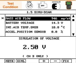
IS THE MAFS SIGNAL CHANGED PROPERLY ACCORDING TO THE SIMULATION OF VOLTAGE ?
YES
Go to step 8
NO
Recheck open or short in the wire between the MAFS terminal 1 and the ECM terminal 8/C230-2.
Go to step 6

Connect the scan tool to the data link connector(DLC) and start the engine.
Go to SIMU-SCAN
Fix the mass air folw quantity current data for the voltage simulation.
- For SIMU-SCAN function information, Go to "Component Inspection" procedure
Apply the simulation voltage to the MAFS terminal 1.
IS THE MAFS SIGNAL CHANGED PROPERLY ACCORDING TO THE SIMULATION OF VOLTAGE ?
YES
Go to step 8
NO
Recheck open or short in the wire between the MAFS terminal 1 and the ECM terminal 8/C230-2.
Go to step 6

Apply the simulation voltage to the ECM terminal 8/C230-2 directly.
IS THE MAFS SIGNAL CHANGED PROPERLY ACCORDING TO THE SIMULATION OF VOLTAGE ?
YES
Recheck open or short in the wire between the MAFS terminal 1 and the ECM terminal 8/C230-2.
Go to step 8
NO
Replace a known - good ECM and recheck. if normal MAFS readings are indicated, replace the ECM
HFM5/3.5 WITH TEMPERAURE SENSOR
Mass air Flow m(kg/h) | Output Voltage UA(V) | Tolerance △m/m[ % ] | Tolerance(Min) UA[V] | Tolerance(Max) UA[V] |
6 | 1.3047 | ± 3 | 1.2951 | 1.3142 |
8 | 1.4044 | ± 3 | 1.3933 | 1.4153 |
10 | 1.4904 | ± 3 | 1.4781 | 1.5026 |
15 | 1.6814 | ± 3 | 1.6654 | 1.6973 |
30 | 2.1159 | ± 3 | 2.0949 | 2.1363 |
60 | 2.6449 | ± 3 | 2.6199 | 2.6692 |
120 | 3.2616 | ± 3 | 3.2323 | 3.2902 |
250 | 4.0015 | ± 3 | 3.9693 | 4.0328 |
370 | 4.4304 | ± 3 | 4.3961 | 4.4638 |
There is a signal voltage or a output value difference due to the contact resistnace or any other reasons between the probe and the sensor terminal.
Perform the test drive
MONITORING FOR PENDING DTC SET ?
YES
Go to the applicable troubleshooting procedure.
NO
System OK