Monitor the "Parameters related to air/fuel ratio(HO2S, MAF, MAP, TPS, ECTS, PCSV, Injector, etc)" on the scantool.

The catalyst’s efficiency is demonstrated by its ability to oxidize CO and hydrocarbon emissions. The Powertrain Control Module (PCM) compares the output signals of the front and rear oxygen sensors to determine whether the output of the rear sensor is beginning to match the output of the front oxygen sensor. Air/fuel mixture compensation keeps the frequency of the front oxygen sensor high due to the changes from rich-to-lean combusition. The catalyst causes the rear oxygen sensor to have a lower frequency. As the catalyst wears, the rear oxygen sensor’s signal trace begins to match the front oxygen sensor’s signal trace. That is because the catalyst becomes saturated with oxygen and cannot use the oxygen to convert hydrocarbon and CO into H₂O and CO₂ with the same efficiency as when it was new. A completely worn catalyst shows a 100% match between the frequency of the front and rear sensors.
If the correction value of air-fuel ratio is lower than the threshold value, ECM sets DTC P0172.
Item | Detecting Condition | Possible Cause | |
DTC Strategy | ● Long-term fuel trim limit | ● Poor connection ● Related sensor ● Intake air system ● Fuel pressure ● ECM | |
General Enable Conditions | ● Coolant temperature 〉 60℃ ● Throttle angle 〈 70% ● Closed loop control enabled ● No transient control phase ● No canister purge phase | ||
Case1 | Enable Conditions | ● Engine load : 37~70 % ● Air mass : 32~900 kg/h | |
Threshold Value | ● multiplicative value (The correction during driving)〈 0.77 | ||
Diagnostic Time | ● 25 sec | ||
Case2 | Enable Conditions | ● Engine speed ≤ 1040 rpm ● Air mass ≤ 16 kg/h | |
Threshold Value | ● additive value (The correction during idling)〈 -7.5% | ||
Diagnostic Time | ● 20 sec | ||
MIL ON Condition | ● 3 driving cycle | ||
Connect scantool to Data Link Connector(DLC).
Warm up the engine to normal operating temperature.
Monitor the "Parameters related to air/fuel ratio(HO2S, MAF, MAP, TPS, ECTS, PCSV, Injector, etc)" on the scantool.

Are the parameters displayed correctly?

▶ Fault is intermittent caused by poor contact in the sensor’s and/or ECM’s connector or wasrepaired and ECM memory was not cleared. Thoroughly check connectors for looseness, poorconnection, bending, corrosion, contamination, deterioration, or damage. Repair or replace as necessary and go to "Verification of vehicle Repair" procedure.

▶ Go to "Terminal and Connector Inspection" procedure
Many malfunctions in the electrical system are caused by poor harness and terminals. Faults can also be caused by interference from other electrical systems, and mechanical or chemical damage.
Thoroughly check connectors for looseness, poor connection, bending, corrosion, contamination, deterioration, or damage.
Has a problem been found?

▶ Repair as necessary and go to "Verification of vehicle Repair" procedure.

▶ Go to "System inspection" procedure.
Air clog check
Check "Air intake system"
▶ Check clog of air-cleaner.
▶ Check deterioration or contamination on throttle body and gasket.
▶ Check contamination, damage, stuck or clog on intake manifold, PCSV, ISCA and injectors.
Is there any problem?

▶ Repair as necessary and go to "Verification of vehicle Repair" procedure

▶ Go to "Fuel pressure check" procedure
Fuel pressure check.
Key "OFF".
Disconnect a fuel pump relay.
Engine start and wait until engine stop. and then key "OFF".
Connect a fuel pump relay.
Connect a fuel pressure guage to a fuel filter by a fuel pressure guage adaptor.
Engine start and measure a fuel pressure.
Specification : Approx. 3.5kg/cm²
Is the fuel pressure normal?

▶ Go to "Component inspection" procedure.

▶ Check the valve in a fuel pressure regulator.
(If it has a problem, fuel happen to be leaked to a return line.)
▶ Check the supply pressure of fuel pump.
▶ Repair as necessary and go to "Verification of vehicle Repair" procedure.
PCV(Positive Crankcase Ventilation) valve check.
Key "OFF".
Disconnect PCV valve.
Check the movement of plunger by putting in and out a thin stick.
Is the movement of plunger normal?

▶ Go to "PCSV check" procedure.

▶ Substitute with a known - good PCV valve and check for proper operation.
▶ If the problem is corrected, replace PCV valve and go to "Verification of Vehicle Repair" procedure.
PCSV check.
Key "OFF".
Disconnect PCSV and vacuum hose.
Apply a vacuum by a hand vacuum gauge on PCSV.
Does PCSV keep the vacuum condition normally?

▶ Go to "Injector check" procedure.

▶ Substitute with a known - good PCSV and check for proper operation.
▶ If the problem is corrected, replace PCSV and go to "Verification of Vehicle Repair" procedure.
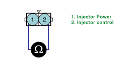
Injector check.
Key "OFF".
Disconnect injectors.
Check clog on injectors.
Measure the resistance between terminal 1 and 2 of injectors(Component side).
ITEM | Specification |
Coil Resistance | 13.8 ~ 15.2Ω at 20℃ (68℉) |

Is the measured resistance within specifications?

▶ Go to "Sensors related to air/fuel ratio check" procedure.

▶ Repair or replace as necessary. And then, go to "Verification of Vehicle Repair" procedure.
Sensors related to air/fuel ratio check.
Check the output data of sensors related to air/fuel ratio (HO2S, MAPS, TPS, ECTS, PCSV, Injectors, etc) on scantool. (Refer to each DTC guide procedure.)
Are those sensors normal?

▶ Substitute with a known - good ECM and check for proper operation.
▶ If the problem is corrected, replace ECM and go to "Verification of Vehicle Repair" procedure.

Repair or replace as necessary. And then, go to "Verification of Vehicle Repair" procedure.
After a repair, it is essential to verify that the fault has been corrected.
Connect scan tool and select "Diagnostic Trouble Codes(DTCs)" mode.
Clear the DTCs and Operate the vehicle within DTC Enable conditions in General information.
Are any DTCs present ?

▶ Go to the applicable troubleshooting procedure.

▶ System is performing to specification at this time.