3.
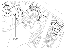
Remove the ECM connector.
When exchanging ECMS, be sure to input injector data (7 digits) of each cylinder into a new ECM using a Hi-scan(pro).
After turning ignition switch off, wait for 30sec..
Remove the battery cable(-).
Remove the ECM connector.
Remove the ECM from the air cleaner assembly.
Install a new ECM with air cleaner assembly.
Fasten four mounting bolts.
Using a Hi-scan(pro), input the injector data (7 digits) into a new ECM as next procedure.
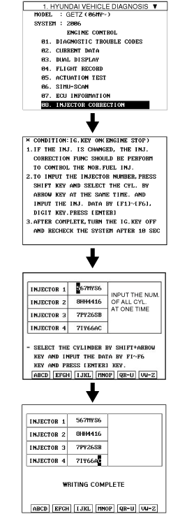
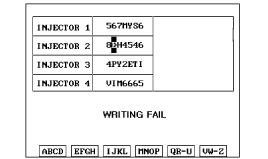
When "WRITING FAIL" is displayed ON Hi-scan(Pro), input injector data (7digits) of each cylinder into a new ECM again as prior procedure.
If the glow lamp is flashed and DTC P1586 is detected ignition switch ON, take proper steps refering to "P1586 DTC Troubleshooting procedure".
TEST ECM GROUND CIRCUIT: Measure resistance between ECM and chassis ground using the backside of ECM harness connector as ECM side check point. If the problem is found, repair it.
Specification (Resistance)
Between terminal 2 of C201-2 connector and chassis ground : 1Ω or less
Between terminal 4 of C201-2 connector and chassis ground : 1Ω or less
Between terminal 6 of C201-2 connector and chassis ground : 1Ω or less
TEST ECM CONNECTOR: Disconnect the ECM connector and visually check the ground terminals on ECM side and harness side for bent pins or poor contact contact pressure. If the problem is found, repair it.
If problem is not found in Step 1 and 2, the ECM could be faulty. If so, replace the ECM with a new one, and then check the vehicle again. If the vehicle operates normally then the problem was likely with the ECM.
RE-TEST THE ORIGINAL ECM : Install the original ECM (may be broken) into a known-good vehicle and check the vehicle. If the problem occurs again, replace the original ECM with a new one. If problem does not occur, this is intermittent problem (Refer to INTERMITTENT PROBLEM PROCEDURE in BASIC INSPECTION PROCEDURE)
