4.
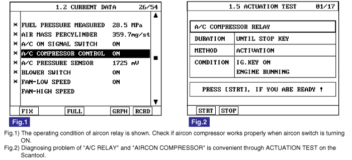
Monitor "A/C COMPRESSOR CONTROL" parameter on the scantool.
specification : A/C switch "ON" : A/C RELAY "ON" (Aircon compressor turns ON and OFF periodically by Aircon pressure S/W. )
A/C switch "OFF" : A/C RELAY "OFF"
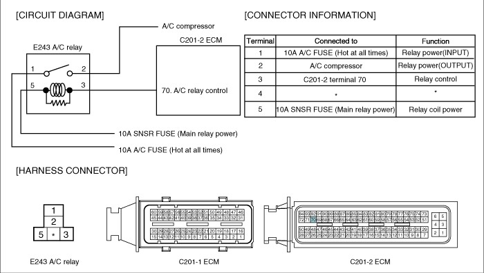
Aircon Relay which is controled by ECM supplies and cut electrical power to Aircon compressor. ECM activates or deactivates Aircon Relay based on inputted signal such as aircon switch siganl and Aircon switch signal.As controlling Aircon Relay, ECM 1)turns OFF aircon compressor at rapid acceleration to retain suffiecient capacity for acceleration, 2)actively performs idle-up function to cope with the change of engine load which happens at aircom compressor operation.
P0647 is set when excessive current is detected in Aircon relay control circuit for more than 1 sec.. This code is due to short to battery in Aircon relay control circuit or internal short in relay component.
Item | Detecting Condition | Possible Cause | ||
DTC Strategy | ● Voltage monitoring | ● A/C relay circuit ● A/C relay component | ||
Enable Conditions | ● IG KEY "ON" | |||
ThresholdValue | ● Short to battery | |||
DiagnosticTime | ● 1.0 sec. | |||
Fail Safe | Fuel Cut | NO | ||
EGR Off | NO | |||
Fuel Limit | NO | |||
MIL | NO | |||
Connect scantool to Data Link Cable (DLC).
Warm engine up to normal operating temperature.
Turn "OFF" electrical devices and A/C.
Monitor "A/C COMPRESSOR CONTROL" parameter on the scantool.
specification : A/C switch "ON" : A/C RELAY "ON" (Aircon compressor turns ON and OFF periodically by Aircon pressure S/W. )
A/C switch "OFF" : A/C RELAY "OFF"
Electrical systems consist of a lot of harness and connectors, poor connection of terminals can cause various problems and damage of component.
Perform checking procedure as follows.
Check damage of harness and terminals : Check terminals for contact resistance, corrosion and deformation.
Check connecting condition of ECM and component connector : Check terminal seperation, damage of locking device and connecting condition between terminal and wiring.
Disconnect the pin which requires checking at mail connector and insert it to the terminal at female connector for checking connecting condition. ( after checking, reconnect the pin at correct position )
Is the problem found?

▶ Repair the trouble causing part and go to "Verification of Vehicle Repair".

▶ Go to "Power Circuit Inspection".
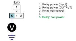
Check power circuit voltage
IG KEY "OFF", ENGINE "OFF".
Disconnect A/C relay.
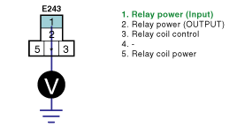
Measure the voltage of A/C relay terminal 1.
specification : 11.5V~13.0V
Is the measured voltage within the specification?
▶ Go to "2. Check IG KEY "ON" power circuit".
▶ Repair problems of 10A FUSE in engineroom junction box and related circuit and go to "Verification of Vehicle Repair".
Check IG KEY "ON" power circuit
IG KEY "OFF", ENGINE "OFF".
Disconnect A/C relay (E243).
IG KEY "ON".
Measure the voltage of glow relay terminal 5.
specification : 11.5V~13.0V
Is the measured voltage within the specification?
▶ Go to "Control Circuit Inspection".
▶ Repair problems of E/R FUSE & RELAY BOX 10A FUSE and related circuit and go to "Verification of Vehicle Repair".
Check monitoring voltage in control circuit
IG KEY "OFF", ENGINE "OFF".
Disconnect A/C relay (E243).
IG KEY "ON".
Measure the voltage of glow relay terminal 3.
specification : 3.2V~3.7V
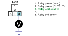
Is the measured voltage within the specification?
▶ Go to "Component Inspection".
▶ When voltage is not detected : Go to "2. Check open in control circuit" as follows.
▶ When high voltage is detected : Repair short to battery and go to "Verification of Vehicle Repair".
Check open in control circuit
IG KEY "OFF", ENGINE "OFF".
Disconnect A/C relay and ECM connector.
Check continuity between glow relay terminal 3 and ECM connector terminal 70.
specification : Continuity ( below 1.0Ω )
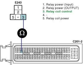
Is the measured resistance within the specification?
▶ Repair short to ground and go to "Verification of Vehicle Repair".
▶ Repair open in control circuit and go to "Verification of Vehicle Repair".
Check A/C relay component resistance
IG KEY "OFF", ENGINE "OFF".
Disconnect A/C relay.
Measure the coil resistance of A/C relay.
specification : 85±5 Ω (20℃)
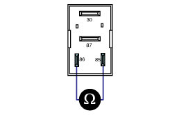
Is the measured resistance within the specification?
▶ Go to "2. Check A/C relay component operation" as follows.
▶ Replace A/C relay and go to "Verification of Vehicle Repair".
Check A/C relay component operation
IG KEY "OFF", ENGINE "OFF".
Disconnect A/C relay
Supplies random B+ and ground to coil sides of A/C relay ( terminal 85, terminal 86)
Check continuity between A/C relay terminal 30 and terminal 87.
specification : When power is supplied : Continuity ( below 1.0Ω )
When power is not supplied : Discontinuity ( Infinite Ω )
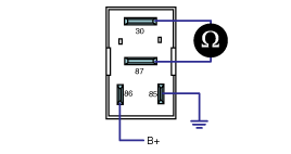
Is the continuity test within the specification?
▶ Go to "Verification of Vehicle Repair".
▶ Replace A/C relay and go to "Verification of Vehicle Repair".
※ Repeat this process 2~3 times.
After a repair, it is essential to verify that the fault is corrected.
After connecting Scantool select "DIAGNOSTIC TROUBLE CODES(DTCs)" mode.
Clear recorded DTC using Scantool.
Drive the vehicle within DTC "Enable conditions" in "General information".
After selecting "DIAGNOSTIC TROUBLE CODES(DTCs)" mode and check if DTC is recorded again.
Are any DTCs recorded ?
▶ Go to the DTC guide of recorded NO. in Scantool.
▶ System operates within specification.