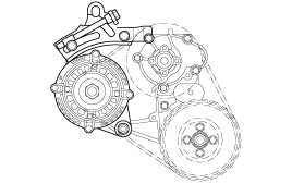
Check that the engine oil level is within the level ragne indicated on the oil dipstick if the oil level is found to have fallen to the lower limit (the "L" mark), refill to the "F" mark.

When refilling, use the same type of engine oil.
DESCRIPTION | 1.3 SOHC | 1.1 SOHC | ||
SPEC | LIMIT | SPEC | LIMIT | |
General Type No. of cylinder Bore Stroke Total displacement Compression ratio Firing order | In-line, SHOC 4 71.5 mm (2.81 in.) 83.5 mm (3.29 in.) 1341 cc 9.5 1 - 3 - 4 - 2 | ← ← 67 mm (2.64 in.) 77 mm (3.03 in.) 1085 cc 9.7 ← | ||
Valve timing Intake valve opens (BTDC) Intake valve closes (ABDC) Exhaust valve opens (BBDC) Exhaust valve closes (ATDC) Valve overlap | 12 52 52 12 24 | 5 35 43 5 10 | ||
Cylinder head Flatness of gasket surface Flatness of manifold mount'g surface Dimension for reworking oversize valve seat hole Intake 0.03 O.S. 0.06 O.S. Exhaust 0.03 O.S. 0.06 O.S. Valve guide hole diameter (intake/exhaust) 0.05 O.S. 0.25 O.S. 0.50 O.S. | Max. 0.03 mm (0.0012 in.) Max. 0.15 mm (0.0059 in.) 28.8 ~ 28.821 mm (1.134 ~ 1.135 in.) 29.1 ~ 29.121 mm (1.146 ~ 1.1467 in.) 34.3 ~ 34.325 mm (1.350 ~ 1.351 in.) 34.6 ~ 34.625 mm (1.362 ~ 1.363 in.) 11.05 ~ 11.068 mm (0.435 ~ 0.436 in.) 11.25 ~ 11.268 mm (0.443 ~ 0.4436in.) 11.50 ~ 11.518 mm (0.453 ~ 0.4535in.) | 0.08 mm (0.00315 in.) 0.3 mm (0.0118 in.) | Max. 0.05mm (0.002 in.) Max. 0.15mm (0.0059 in.) 24.3 ~ 24.321 mm (0.957 ~ 0.9575 in.) 24.6 ~ 24.621 mm (0.968 ~ 0.969 in.) 29.3 ~ 29.321 mm (1.154 ~ 1.1544 in.) 29.6 ~ 29.621 mm (1.165 ~ 1.166 in.) 10.05 ~ 10.068 mm (0.396 ~ 0.3963 in.) 10.25 ~ 10.268 mm (0.403 ~ 0.404 in.) 10.50 ~ 10.518 mm (0.413 ~ 0.414 in.) | 0.1 mm (0.00394 in.) 0.3 mm (0.0118 in.) |
Camshaft Cam height intake Cam height exhaust Journal diameter Bearing oil clearance End play | 42.8575 mm (1.687 in.) 42.7354 mm (1.682 in.) 30 mm (1.181 in.) 0.045 ~ 0.085 mm (0.0018 ~ 0.0033 in.) 0.07 ~ 0.28 mm (0.0027 ~ 0.011 in.) | 42.3575 mm (1.667 in.) 42.2624 mm(1.664 in.) | 34.8729 mm (1.373 in.) 35.1258 mm (1.383 in.) 41 mm (1.614 mm) 0.045 ~ 0.085 mm (0.0018 ~ 0.0033 in.) 0.07 ~ 0.19 mm (0.0027 ~ 0.0074 in.) | 34.7729 mm (1.369 in.) 35.0258 mm (1.379 in.) |
Crankshaft Journal diameter Pin diameter Bend Out of roundness of journal and pun Taper of journal and pin End play Undersize of Pin 0.25 0.50 0.75 Undersize of Journal 0.25 0.50 0.75 Main bearing oil clearance No. 1,2,4,5 No. 3. | 50 mm (1.97 in.) 45 mm (1.77 in.) 0.03 mm (0.0018 in.) Max. 0.005 Max. 0.005 0.05 ~ 0.175 mm (0.002 ~ 0.007 in.) 44.725 ~ 44.740 mm (1.76 ~ 1.761 in.) 44.475 ~ 44.490 mm (1.75 ~ 1.751 in.) 44.225 ~ 44.240 mm (1.74 ~ 1.741 in.) 49.727 ~ 49.742 mm (1.957 ~ 1.958in.) 49.477 ~ 49.492 mm (1.948 ~ 1.9485in.) 49.227 ~ 49.242 mm (1.938 ~ 1.9386in.) 0.022 ~ 0.040 mm (0.0086 ~ 0.0016 in.) 0.028 ~ 0.046 mm (0.0011 ~ 0.0018 in.) | 0.25 mm(0.0098 in.) 0.1 mm (0.00394 in.) | 42 mm (1.65 in.) 38 mm (1.496 in.) 0.03 mm (0.00118 in.) ← ← 0.05 ~ 0.25 mm (0.002 ~ 0.0098 in.) 37.735 ~ 37.75 mm (1.486 ~ 1.4862 in.) 37.485 ~ 37.50 mm (1.4751.476 in.) 41.735 ~ 41.75 mm (1.643 ~ 1.644 in.) 41.485 ~ 41.50 mm (1.633 ~ 1.634 in.) 0.02 ~ 0.038 mm (0.00078 ~ 0.0015 in.) 0.02 ~ 0.038 mm (0.00078 ~ 0.0015in.) | |
Valve Stem diameter Intake Exhaust Face angle Thickness of valve head (margin) Intake Exhaust Valve stem to valve guide clearance Intake Exhaust | 5.955 ~ 5.97 mm (0.234 ~ 0.235 in.) 5.935 ~ 5.95 mm (0.2336 ~ 0.234 in.) 45° ~ 45.5° 1.1 mm (0.043 in.) 1.3 mm (0.051 in.) 0.03 ~ 0.06 mm (0.0012 ~ 0.0024 in.) 0.05 ~ 0.08 mm (0.0020 ~ 0.0031 in.) | 0.8mm(0.031in.) 1 (0.039 in.) 0.1 mm (0.0039 in.) 0.15 mm (0.006 in.) | 5.48 ~ 5.465 mm (0.216 ~ 0.2151 in.) 5.45 ~ 5.43 mm (0.215 ~ 0.213 in.) ← 0.8 mm (0.031 in.) 1.2 mm (0.047 in.) 0.02 ~ 0.047 mm (0.008 ~ 0.0018 in.) 0.05 ~ 0.082 mm (0.002 ~ 0.0032 in.) | 0.5 mm (0.0197 in.) 0.9 mm (0.035 in.) 0.1 mm (0.0039 in.) 0.15 mm (0.006 in.) |
Valve guide Length Intake Exhaust Service oversize | 12.8 mm (0.504 in.) 12.8 mm (0.504 in.) 0.05, 0.25, 0.50 | 10.05 mm (0.396 in.) 10.05 mm (0.396 in.) ← | ||
Valve seat Width of seat contact Intake Exhaust Seat angle Service oversize | 0.8 ~ 1.2 mm (0.031 ~ 0.047 in.) 1.3 ~ 1.7mm (0.051 ~ 0.067 in.) 45° 0.3, 0.6 | 0.9 ~ 1.3 mm (0.035 ~ 0.05 in.) 0.9 ~ 1.3 mm (0.035 ~ 0.05 in.) ← ← | ||
Valve spring Free length (Installed height) Load Out of squareness Valve clearance (cold : 20°C)/Warm:80°C) Intake Cold : 20°C Warm : 80°C Exhaust Cold : 20°C Warm : 80°C | 44 mm (1.732 in.) 21.6kg/35mm, 45.1kg/27.2mm Max 1.5 - - | 40.5 mm (1.594in.) 15.6kg / 32.0 mm, 33.3 kg / 24.5 mm 0.1 mm 0.2 mm 0.17 mm 0.25 mm | ||
Cylinder block Cylinder bore Out of roundness of cylinder bore Taper of cylinder bore Flatness of gasket surface | 71.5 ~ 71.53 mm (2.815 ~ 2.816 in.) Max. 0.01 - Max. 0.05 | 0.1 mm (0.0039 in.) | 67 ~ 67.3 mm (2.64 ~ 2.65 in.) | |
Piston Dameter Piston to cylinder clearance | 71.47 ~ 71.50 mm (2.814 ~ 2.815 in.) 0.02 ~ 0.04 mm (0.0078 ~ 0.00157 in.) | 66.97 ~ 67.0 mm (2.636 ~ 2.65 in.) ← | ||
Piston ring No. of rings per piston Compression ring Oil ring Compression ring type No. 1 No. 2 Oil ring type Side clearance No. 1 No. 2 Oil ring End gap No. 1 No. 2 Oil ring side rail Sevice oversize | 3 2 1 Inside bevel type, steel Taper type 3-piece type 0.04 ~ 0.085 mm (0.0016 ~ 0.0033 in.) 0.04 ~ 0.085 mm (0.0016 ~ 0.0033 in.) 0.06 ~ 0.15 mm (0.0023 ~ 0.006 in.) 0.20 ~ 0.35 mm (0.0079 ~ 0.0138 in.) 0.37 ~ 0.52 mm (0.015 ~ 0.02 in.) 0.2 ~ 0.7 mm (0.008 ~ 0.028 in.) 0.25, 0.50, 0.75, 1.0 | 0.1 mm (0.00394 in.) 0.1 mm (0.00394 in.) 1 mm (0.0394 in.) 1 mm (0.0394 in.) 1 mm (0.0394 in.) | ← ← ← ← 0.03 ~ 0.07 mm (0.0012 ~ 0.0027 in.) 0.02 ~ 0.06 mm (0.0008 ~ 0.0023 in.) 0.08 ~ 0.15 mm (0.003 ~ 0.006 in.) 0.15 ~ 0.30 mm (0.006 ~ 0.012 in.) 0.30 ~ 0.50 mm (0.012 ~ 0.02 in.) ← ← | |
Connecting rod Bend Twist Connecting rod big end to crankshaft side clearance Piston pin press in load Bearing oil clearance | Max. 0.05 per 100 mm Max. 0.1 per 100mm 0.10 ~ 0.25 mm (0.004 ~ 0.01 in.) 1250 ± 500 kg 0.018 ~ 0.036 mm (0.0007 ~ 0.0014 in.) | 0.4mm(0.016in.) 0.1mm(0.0039in.) | ← 0.012 ~ 0.041 mm (0.0004 ~ 0.0016 in.) | |
Flywheel Runout | 0.1mm (0.0014 in.) | 0.13mm (0.005in.) | 0.1 mm (0.004 in.) | 0.13 mm (0.005 in.) |
Oil pressure at curb idle speed (oil temp. 90~110°C) | 1.5kg/cm² | |||
Oil pump Clearance between outer circum ference and front Clearance between roter axial side and front case Tip clearance between outer and inner roter | 0.12 ~ 0.18 mm (0.0047 ~ 0.0071 in.) 0.04 ~ 0.065 mm (0.0016 ~ 0.0026 in.) 0.025 ~ 0.069 mm (0.0010 ~ 0.0027 in.) | 0.10 ~ 0.18 mm (0.0039 ~ 0.0071 in.) 0.04 ~ 0.095 mm (0.0016 ~ 0.0037 in.) 0.18 ~ 0.060 mm (0.007 ~ 0.0024 in.) | ||
Relief spring Free length Load | 46.6 mm (1.8346 in.) 61kg at 40.1 mm (13.4216 at 1.578 in.) | 38.6 mm (1.519 in.) 3.65 kg at 33.0 mm (8.16 at 1.299 in.) | ||
Cooling method | Water-cooled, Pressurized, Forced circulation with electrical fan | ← | ||
Cooling sys. Quantity | 6.2 lit (6.55 U.S qts 5.46 lmp qts) | 6.0 lit (6.34 U.S. qts, 5.28 lmp qts) | ||
Thermostat Type Normal opening temp. Opening temp. range Wide opening temp. | Wax pellet type with jiggle valve 82°C 80.5 ~ 83.5°C 95°C | ← ← ← ← | ||
Radiator cap Main valve opening pressure Main valve colseing pressure Vacuum valve opening preesur | 86.1 ~ 124.5 kpa 83.4 kpa -86.6 kpa | ← ← ← | ||
Air cleaner Type Element | Dry type Unwoven cloth type | ← ← | ||
Exhaust pipe Muffler Suspension sys. | Expansion resonance type Rubber hanger type | ← ← | ||
Item | Nm | kg.cm | lb.ft |
Cylinder Block Left engine support bracket bolt Oil pressure switch | 30 ~ 42 13 ~ 15 | 300 ~ 420 130 ~ 150 | 22 ~ 31 9.6 ~ 11 |
Cylinder head Cylinder head bolt Intake/manifold bolts or nuts Exhaust manifold nut Recker cover bolt Recker arm shaft bolt Camshaft bolt Rear plate bolt | (23 ~ 27) + (60° ~ 62°) + (60° ~ 62°) 15 ~ 20 15 ~ 20 8 ~ 10 20 ~ 24 20 ~ 27 8 ~ 10 | (230 ~ 270) + (60° ~ 62°) + (60° ~ 62°) 150 ~ 200 150 ~ 200 80 ~ 100 20 ~ 240 200 ~ 270 80 ~ 100 | (17 ~ 20) + (60° ~ 62°) + (60° ~ 62°) 11 ~ 15 11 ~ 15 6 ~ 7 15 ~ 18 15 ~ 20 6 ~ 7 |
Main Moving parts Connecting rod cap nut Crankshaft bearing cap bolt Flywheel M/T bolt Drive plate A/T bolt | 32 ~ 35 55 ~ 60 130 ~ 140 130 ~ 140 | 320 ~ 350 550 ~ 600 1300 ~ 1400 1300 ~ 1400 | 24 ~ 26 41 ~ 44 96 ~ 103 96 ~ 103 |
Timing Belt Crankshaft sprocket bolt Camshaft sprocket bolt Timing belt tensioner bolt Timing belt cover bolt Front case bolt | 140 ~ 150 80 ~ 100 20 ~ 27 10 ~ 12 12 ~ 15 | 1400 ~ 1500 800 ~ 1000 200 ~ 270 100 ~ 120 120 ~ 150 | 103 ~ 111 59 ~ 74 15 ~ 20 7 ~ 9 9 ~ 11 |
Engine Mounting Engine mounting insulator bolts Engine mounting bracket to engine (large) nut Engine mounting bracket to engine nuts and bolts Transaxle mount insulator bolt Transaxle insulator bracket to side member bolts Rear roll rod bracket bolt Rear roll rod bracket to cross member | 35 ~ 55 70 ~ 95 35 ~ 55 70 ~ 95 35 ~ 55 35 ~ 55 70 ~ 95 | 350 ~ 550 700 ~ 950 350 ~ 550 700 ~ 950 350 ~ 550 350 ~ 550 700 ~ 950 | 25.8 ~ 40.6 51.6 ~ 70 25.8 ~ 40.6 51.6 ~ 70 25.8 ~ 40.6 25.8 ~ 40.6 51.6 ~ 70 |
Oil filter Oil pan bolts Oil pan drain plug Oil screen bolts | 12 ~ 16 6 ~ 8 35 ~ 45 15 ~ 22 | 120 ~ 160 60 ~ 80 350 ~ 450 150 ~ 220 | 9 ~ 12 4 ~ 6 26 ~ 33 11 ~ 16 |
Timing belt upper cover bolts Timing belt lower cover bolts Surge tank to inlet manifold nuts and bolts | 10 ~ 12 10 ~ 12 15 ~ 20 | 100 ~ 120 100 ~ 120 150 ~ 200 | 7 ~ 9 7 ~ 9 11 ~ 15 |
Cooling system Generator support and nut Generator lock bolt Generator brace mounting bolt Coolant pump pulley Coolant pump bolt Coolant temperature gauge unit Coolant temperature sensor Coolant outlet fitting bolt Thermostat housing bolt | 20 ~ 25 15 ~ 22 20 ~ 28 8 ~ 10 12 ~ 15 10 ~ 12 15 ~ 20 17 ~ 20 15 ~ 20 | 200 ~ 250 150 ~ 220 200 ~ 280 80 ~ 100 120 ~ 150 100 ~ 120 150 ~ 200 170 ~ 200 150 ~ 200 | 15 ~ 18 11 ~ 16 15 ~ 21 6 ~ 7 9 ~ 11 7 ~ 9 11 ~ 15 13 ~ 15 11 ~ 15 |
Intake and Exhaust system Air cleaner body mounting bolts Resonator mounting bolts Throttle body to surge tank bolts Oxygen sensor to exhaust manifold Front exhaust pipe to exhaust manifold nuts Front exhaust pipe bracket bolts Front exhaust pipe to cataiytic converter bolts | 8 ~ 10 4 ~ 6 15 ~ 20 50 ~ 60 30 ~ 40 30 ~ 40 40 ~ 60 | 80 ~ 100 40 ~ 60 150 ~ 200 500 ~ 600 300 ~ 400 300 ~ 400 400 ~ 600 | 6 ~ 7 2.9 ~ 4.3 11 ~ 15 37 ~ 44 22 ~ 30 22 ~ 30 30 ~ 44 |
Item | Nm | kg.cm | lb.ft |
Cylinder block Left engine support bracket Oil pressure switch | 45 ~ 55 15 ~ 22 | 450 ~ 550 150 ~ 220 | 33 ~ 41 11 ~ 16 |
Cylinder head Cylinder head bolt Cold engine Hot engine Inkake/manifold to cylinder head nuts and bolts Exhaust manifold nut Rocker cover bolt Rocker arm shaft bolt | 60 ~ 70 70 ~ 75 15 ~ 20 15 ~ 20 8 ~ 10 27 ~ 32 | 600 ~ 700 700 ~ 750 150 ~ 200 150 ~ 200 80 ~ 100 270 ~ 320 | 44 ~ 52 52 ~ 56 11 ~ 15 11 ~ 15 6 ~ 7 20 ~ 24 |
Main Moving Connecting rod cap nut Crankshaft bearing cap bolt Flywheel M/T bolt | 20 ~ 23 50 ~ 55 70 ~ 80 | 200 ~ 230 500 ~ 550 700 ~ 800 | 15 ~ 17 37 ~ 41 52 ~ 59 |
Timing Belt Crankshaft pulley bolt Camshaft sprocket bolt Timing belt tensioner bolt Timing belt cover bolt Front case bolt | 140 ~ 150 80 ~ 100 22 ~ 30 10 ~ 12 8 ~ 10 | 1400 ~ 1500 800 ~ 1000 220 ~ 300 100 ~ 120 80 ~ 100 | 103 ~ 111 59 ~ 74 16 ~ 22 7 ~ 9 6 ~ 7 |
Engine Mounting Engine mount insulator bolts Engine mounting bracket to engine (large)nut Engine mounting bracket to engine nuts and bolt Teransaxle mount insulator bolt Rear roll rod bracket bolt Rear roll rod bracket to cross member bolt OIl filter Oil pan bolts Oil pan drain plug Oil screen bolts Timing belt cover bolts Surge tank to inlet manifold nuts and bolts | 35 ~ 55 70 ~ 95 35 ~ 55 70 ~ 95 35 ~ 55 70 ~ 95 12 ~ 16 6 ~ 8 35 ~ 45 15 ~ 22 10 ~ 12 15 ~ 20 | 350 ~ 550 700 ~ 950 350 ~ 550 700 ~ 950 350 ~ 550 700 ~ 950 120 ~ 160 60 ~ 80 350 ~ 450 150 ~ 220 100 ~ 120 150 ~ 200 | 25.8 ~ 40.6 51.6 ~ 70 25.8 ~ 40.6 51.6 ~ 70 25.8 ~ 40.6 51.6 ~ 70 9 ~ 12 4 ~ 6 26 ~ 37 11 ~ 16 7 ~ 9 11 ~ 15 |
Generator support bolt and nut Generator brace bolt Geneator brace mounting bolt Coolant pump pulley Coolant pump bolt Coolant temperature sender Collant temperature sensor Coolant outlet fitting bolt Thermostat housing bolt Air cleaner body mounting bolts Air intake hose clamp Air duct assembly mounting bolt Throttle body to surge tank bolts Exhaust manifold cover to exhaust manifold bolts Oxygen sensor to exhaust manifold Front exhaust pipe to exhaust manifold nuts Front exhaust pipe bracket bolts Front exhaust pipe to catalytic convrter bolts Main muffler hanger support bracket bolts | 20 ~ 25 12 ~15 20 ~28 8 ~ 10 12 ~ 15 10 ~ 12 15 ~ 20 15 ~ 20 8 ~ 10 8 ~ 10 3 ~ 5 8 ~ 10 15 ~ 20 8 ~ 10 50 ~ 60 30 ~ 40 30 ~ 40 40 ~ 60 10 ~ 15 | 200 ~ 250 120 ~ 150 200 ~ 280 80 ~ 100 120 ~ 150 100 ~ 120 150 ~ 200 150 ~ 200 80 ~ 200 80 ~ 100 30 ~ 50 80 ~ 100 150 ~ 200 80 ~ 100 500 ~ 60 300 ~ 400 300 ~ 400 400 ~ 600 100 ~ 150 | 15 ~18 9 ~ 11 15 ~ 21 6 ~ 7 9 ~ 11 7 ~ 9 11 ~ 15 11 ~ 15 6 ~ 7 6 ~ 7 2 ~ 4 6 ~ 7 11 ~ 15 6 ~ 7 37 ~ 44 22 ~ 30 22 ~ 30 30 ~ 44 7 ~ 11 |
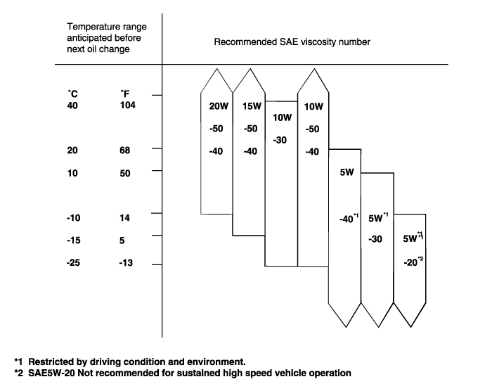
For best performance and maximum protection of all types of operation, select only those lubricants which :
Satisfy the requirements of the API classification.
Have proper SAE grade number for expected ambient temperature range.
Lubricant that does not have both an SAE grade number and an API service classification on the container should not be used.
CHECKING ENGINE OIL
Position the vehicle on a level surface.
Warm up the engine.
If a vehicle has been out of service for a prolonged period of time, warm up the engine for approximately 20 minutes.
Turn off the engine, and wait 2 or 3 minutes, then check the oil level.
Check that the engine oil level is within the level ragne indicated on the oil dipstick if the oil level is found to have fallen to the lower limit (the "L" mark), refill to the "F" mark.

When refilling, use the same type of engine oil.
Check that the oil is not dirty or contaminated with coolant or gasoline and that it has proper viscosity.
Be careful not to brun yourself, as the engine oil is hot.
Run the enigne until it reaches normal operating temperature.
Turn off the engine.
Remove the oil filler cap and the drain plug (on the oil pan). Drain the engine oil.
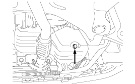
Install and tighten the drain plug to the specified torque.
Tightening torque
Drain plug : 35 ~ 45 Nm (350 ~ 450 kg.cm, 24 ~ 33 lb.ft)
Whenever tightening the oil drain plug, use a new drain plug gasket.
Fill the crankcase with fresh engine oil through the oil filler cap opening.
Drain and Refill Without oil filter
1.3 L : 3.0 liter (3.17 U.S. qts., 2.64 lmp. qts.)
1.1 L : 2.8 liter (2.96 U.S. qts., 2.46 lmp. qts.)
Drain and Refill With oil filter
1.3 L : 3.3 liter (3.48 U.S. qts., 2.90 lmp. qts.)
1.1 L : 3.1 liter (3.28 U.S. qts., 2.73 lmp. qts.)
Install the oil filler cap.
Start and run the engine.
Turn off the engine and then check the oil level. Add oil if necessary.
All Hyundai engines are dquipped with a high quality, disposable oil filter. This filter is recommended as a replacement filter on all vehicles. The quality of replacement filters varies considerably. Only high quality filters should be used to assure the most efficient service. Make sure that the rubber gasket from the old oil filter is completely removed from the contact surface on the engine block be fore installing the new filter.
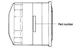
PROCEDURE FOR REPLACING THE OIL FILTER
Be careful not to burn ylurself, as the engine and engine oil are not.
Use a filter wrench to remove the oil filter.
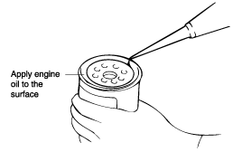
Before installing the new oil filter on the engine, apply clean engine oil to the surface of the rubber gasket.
Tighten the oul filter to the specified torque.
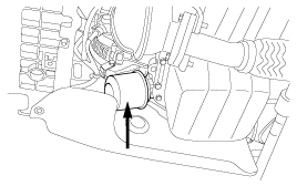
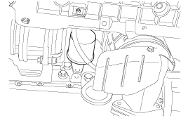
Tightening torque
Oil filter : 12 ~ 16 Nm (120 ~ 160 kg.cm, 9 ~ 12 lb.ft)
Run the engine to check for engine oil leaks.
After turning off the engine, check the oil level and add oil as necessary.
Wait until the engine is cool, then carefully remove the radiator cap.
Confirm that the coolant level is up to the filler neck.
Install a radiator cap tester to the radiator filler neck and apply 140 KPa (1.4 kg/cm², 20 psi) pressure. Hold it for two minutes in that condition, while checking for leakage from the radiator, hoses or connections.
Radiator coolant may be extremely hot. Do not open the system because hot, or scalding water could gush out causing personal injury. Allow the vehicle to cool before servicing this system.
Be sure to clean away any moisture from the places checked completely.
When the tester is removed, be careful not to spill any coolant from it.
Be careful, when installing and removing the tester and when testing, not to deform the filler neck of the radiator.
If there is leakage, repair or replace with the apropriate part.
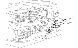
Remove the radiator cap. Wet its seal with engine coolant, then install it on the tester.
Increase the pressure until the gauge stops moving.
Main valve opening pressure :
78 ~ 108 kPa (0.8 ~ 1.1 kg/cm², 11.3 ~ 15.6 psi)
Limit : 65 kPa (0.66 kg/cm², 9.2 psi)
Check that the pressure level is maintained at or above the limit.
Replace the radiator cap if the reading does not remain at or above the limit.
Be sure that the cap is clean before testing, since rust or other foreign material on the cap seal will cause an incorrect reading.
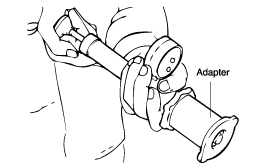
When pouring engine coolant, be sure to shut the relay box lid and not to let coolant spill on electrical parts or the paint. If any coolant spills, rinse it off immediately.
Slide the heater temperature control lever to maximum heat. Make sure the engine and radiator are cool to the touch.
Remove the radiator cap.
Loosen the drain plug and drain the coolant.
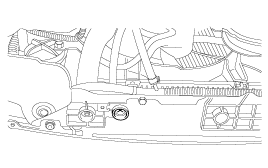
Tighten the radiator drain plug securely.
Remove, drain and reinstall the reservior.
Fill the tank halfway to the MAX mark with water, then up to the MAX mark with antifreeze.
Pour coolant into the radiator up to the base of the filler neck, and install the radiator cap loosely.
Start the engine and let it run until it warms up (the radiator fan comes on at least twice)
Turn off the engine. Check the level in the radiator, add coolant if needed.
Put the radiator cap on tightly, then run the engine again and check for leaks.
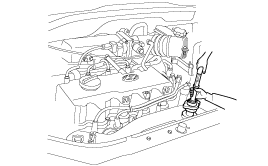
Measure the specific gravity of the coolant with a hydrometer.
Mesure the coolant temperature and calculate the concentration from the relation between the specific gravity and temperature, using the following table for reference.
Coolant temperature °C (°F) and specific gravity | Freezing temperature °C (°F) | Safe operating temperature °C (°F) | Coolant concentration (Specific volume) | ||||
10 (50) | 20 (68) | 30 (86) | 40 (104) | 50 (122) | |||
1.054 | 1.050 | 1.046 | 1.042 | 1.036 | -16 (3.2) | -11 (12.2) | 30% |
1.063 | 1.058 | 1.054 | 1.049 | 1.044 | -20 (-4) | -15 (5) | 35% |
1.071 | 1.067 | 1.062 | 1.057 | 1.052 | -25 (-13) | -20 (-4) | 40% |
1.079 | 1.074 | 1.069 | 1.064 | 1.058 | -30 (-22) | -25 (-13) | 45% |
1.087 | 1.082 | 1.076 | 1.070 | 1.064 | -36 (-32.8) | -31 (-23.8) | 50% |
1.095 | 1.090 | 1.084 | 1.077 | 1.070 | -42 (-44) | -37 (-35) | 55% |
1.103 | 1.098 | 1.092 | 1.084 | 1.076 | -50 (-58) | -45 (-49) | 60% |
If the concentration of the coolant is below 30%, its anti-corrosion properties will be adversely affected.
If the concentration is above 60%, both the antifreeze and engine cooling property will decrease, affecting the engine adversely. For these reasons, be sure to maintain the concentration level within the specified range.
Do not use together with another brand's product.
Antifreeze | Mixture ratio of anti freeze in coolant |
ETHYLENE GLYCOL BASE FOR ALUMINUM | 50% [Except tropical areas] 40% [Tropical areas] |
Befor checking engine compression, check the engine oil level. Also check that the starter motor and battery are all in normal operating condition.
Check the DTC and resetting the ECM will erase any stored DTCs.
Stsrt the engine and wait until engine coolant temperature reaches 80~95°C (176~205°F).
Disconnect the fuel pump connector.
Turn off engine and disconnect the spark plug cables.
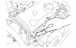
Remove the spark plug.
Disconnect the I.G. connector.
Crank the engine to remove any foreign material in the cylinders.
Insert the compression gauge into the spark plug hole.
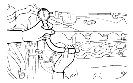
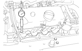
Depress the accelerator pedal to open the throttle fully.
Crank the engine and read the gauge.
Standard value : 1500 kpa (15.5 kg/cm², 220 psi)
Limit : 1200 kpa (12.5 kg/cm², 178 psi)
Repeat steps 9 to 11 over all cylinders, ensuring that the pressure differential for each of the cylinders is within the specified limit.
Limit : Max. 150 kpa (1.5 kg/cm², 21 psi)
between cylinders
If a cylinder's compression or pressure differential is outside the specification, add a small amount of oil through the spark plug hole, and repeat steps 9 to 12.
If the addition of oil makes the compression to rise, it is likely that there may be wear between the piston ring and cylinder wall.
If compression remains the same, valve seizure, poor valve seating or a compression leak from the cylinder head gasket are all possible causes.
Tightening torque
Spark plug : 20~30 Nm (200~300 kg.cm, 14~22 lb.ft)
Turn the steering wheel fully counter clock wise.
Lift the vehicle by using of jack.
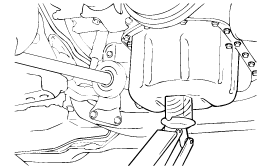
Remove the engine support bracket.
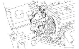
Loosen the coolant pump pulley mounting bolt and loosen the generator belt tension adjustment bolt.
Remove the coolant pump pulley, generator belt, power steering pulley and power steering belt.
Remove the timing cover upper side mounting bolt (4EA).
Remove the crankshaft pulley.
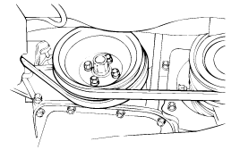
Turn crankshaft to place clockwise in No.1 cylinder at top head center on compression stroke.
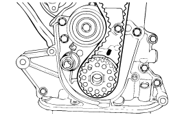
Turn the crankshaft clock wise. If counter clock wise, tension is not available.
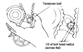
Loosen the tensioner bolt 1~2 turn and tension the belt by tensioner spring.
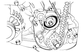
Turn crankshaft clockwise as much as two camshaft sprocket teeth.
Tighten the tensioner bolt of slot side of first and then tighten the bolt of pivot side.
Rotate the crankshaft pulley two turns clockwise so that the timing belt positions on the pulleys.
Pust the arrow direction on tensioner, measure the engagement between camshaft sprocket 'A' part belt and sprocket.
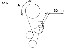
Check the tension of timing belt. (1.3L)
When the tensioner and the tension side of the timing belt are pushed in horizontally with a moderate force [approx. 49N (11 lb)], the timing belt log end is approx. half of the tensioner mounting bolt head radius (cross flats) away from the bolt head center.
Install the timing belt cover.
Tightening torque :
10 ~ 12 Nm (100 ~ 120 kg.cm, 7.2 ~ 8.7 lb.ft)
Install the crankshaft pulley.
Install the coolant pump pulley.
Install V-belt and adjust the belt tension.
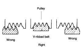
Check that the belts are not damaged and are properly fit for the pulley grooves.
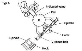
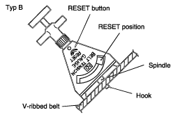
Apply 100 N (22 lbs.) force to the back and midway portion of the belt between the pulleys as shown in the illustration, measure the amount of deflection with a tension gauge.
When installing the V-ribbed belt, check that the V-ribs are properly aligned.
If noise or slippage is detected, check the belt for wear, damage, or breakage on the pulley contact surface, and check the pulley for scoring. Also check the amount that the belt is deflected.
Items | Adjustment | ||
New | Used | ||
For alternator | 1.1 L : Deflection mm (in.) | 8.5 ~ 9.5 (0.33 ~ 0.37) | 10 (0.39) |
1.3 L : Deflection mm (in.) | 7.5 ~ 9.0 (0.29 ~ 0.35) | 10 (0.39) | |
The belt tension must be measured half - way between the specified pulleys.
When a new belt is installed, adjust the tension to the central value of the standard range indicated under "New" in the above table. Let the engine idle for 5 minutes or more, and check the standard value indicated under "Inspection".
When adjusting a belt which has been used, or newly installed, after 5 minutes or more of operation, refer to the standard value indicated under "Used" in the above table.
Refer to the standard value indicated under "Inspection" for periodic inspections.
When measuring, turn the reset button in the direction of the arrow and set the gauge needle to the RESET position.
If the tension gauge is removed from the belt, the needle will still indicate the tension. Read the tension value after removing the gauge.
If the belt is too loose, it will cause noise or sudden wear.
If the belt is too tight, the engine coolant pump bearing or the alternator can get damaged.
Loosen the alternator nut "A" and the tension adjuster lock the bolt "B"
Using the tension adjuster bolt, adjust the belt tension to the specification.
Tighten the adjuster lock bolt "B".
Tighten the alternator nut "A".
Check the tension or the deflection of belt, readjust if necessary.
Tightening torque Alternator support nut A : 20 ~ 25 Nm (200 ~ 250 kg.cm, 15 ~ 18 lb.ft) Alternator lock bolt B : 15 ~ 22 nM (150 ~ 220 kg.cm, 11 ~ 16 lb.ft) Alternator brace mounting bolt : 20 ~ 28 Nm (200 ~ 280 kg.cm, 15 ~ 21 lb.ft) |
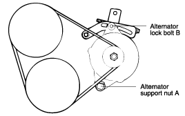
Tightening torque Alternator support bolt and nut : 20 ~ 25 Nm (200 ~ 250 kg.cm, 14 ~ 18 lb.ft) Alternator lock bolt B : 12 ~ 15 Nm (120 ~ 150 kg.cm, 9 ~ 11 lb.ft) Alternator brace mounting bolt : 20 ~ 27 Nm (200 ~ 270 kg.cm, 15 ~ 20 lb.ft) |
