Is the problem found?

▶ Repair the trouble causing part and go to "Verification of Vehicle Repair".

▶ Go to "Power Circuit Inspection".
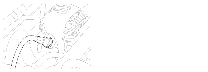
O2 sensor installed at exhaust manifold is linear O2 sensor and it senses O2 density of exhaust gas for accurate EGR control through fuel correction. It also limits smoke which is generated by reach air-fuel mixture at engine maximum loading condition. ECM controls pumping current in order to fit λ-value from linear O2 sensor to 1.0.
Lean air-fuel mixture(1.0<λ<1.1) : ECM supplies pumping current to O2 sensor (+pumping current) and activates it for O2 sensor to have the characteristic at λ=1.0 (0.0 pumping current). With the value of pumping current supplied to O2 sensor, ECM detects O2 density of exhaust gas.
Rich air-fuel mixture(0.9<λ<1.0) : ECM takes away pumping current from O2 sensor (-pumping current) and deactivates it for O2 sensor to have the characteristic at λ=1.0 (0.0 pumping current). With the value of pumping current taken away from O2 sensor, ECM detects O2 density of exhaust gas.
This performance is the most active and fast at normal operating temp.(450℃~600℃) thus, in order to reach normal operating temp. and last at that temp., heater(heating coil) is integrated with O2 sensor.Heater coil is controlled by ECM as PWM. the resistance of heater coil is low when coil is cold thus, current through it increases while resistance is high when coil is hot thus, current decreases. With this principle, O2 sensor temp. is measured and O2 sensor heater operation varies based on the data.
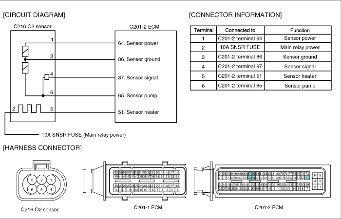
P2238 is set when 1) short to ground in signal line(terminal 4), ground line(terminal 3), power line(terminal 1), pumping current line(terminal 6) or 2) open in ground line is detected. This code is due to the problem of O2 sensor circuit.
Item | Detecting Condition | Possible Cause | ||
DTC Strategy | ● Voltage monitoring | ● O2 sensor circuit ● O2 sensor component | ||
Enable Conditions | ● Engine running | |||
ThresholdValue | ● Short to battery in O2 sensor circuit ● Open in O2 sensor circuit | |||
DiagnosticTime | ● 2.0 sec. | |||
Fail Safe | Fuel Cut | NO | ||
EGR Off | NO | |||
Fuel Limit | NO | |||
MIL | NO | |||
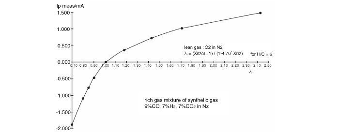
λ value | 0.65 | 0.70 | 0.80 | 0.90 | 1.01 | 1.18 | 1.43 | 1.70 | 2.42 | Air |
Pumping current | -2.22 | -1.82 | -1.11 | -0.50 | 0.00 | 0.33 | 0.67 | 0.94 | 1.38 | 2.54 |
Electrical systems consist of a lot of harness and connectors, poor connection of terminals can cause various problems and damge of component.
Perform checking procedure as follows.
Check damage of harness and terminals : Check terminals for contact resistance, corrosion and deformation.
Check connecting condition of ECM and component connector : Check terminal seperation, damage of locking device and connecting condition between terminal and wiring.
Disconnect the pin which requires checking at male connector and insert it to the terminal at female connector for checking connecting condition. ( after checking, reconnect the pin at correct position. )
Is the problem found?

▶ Repair the trouble causing part and go to "Verification of Vehicle Repair".

▶ Go to "Power Circuit Inspection".
Check voltage & waveform in sensor power circuit
IG KEY "OFF", ENGINE "OFF".
Disconnect O2 sensor connector.
IG KEY "ON".
Measure the voltage of O2 sensor connector terminal 1.
Monitor the waveform in O2 sensor connector terminal 1.
Specification : Measured voltage : 2.0 V
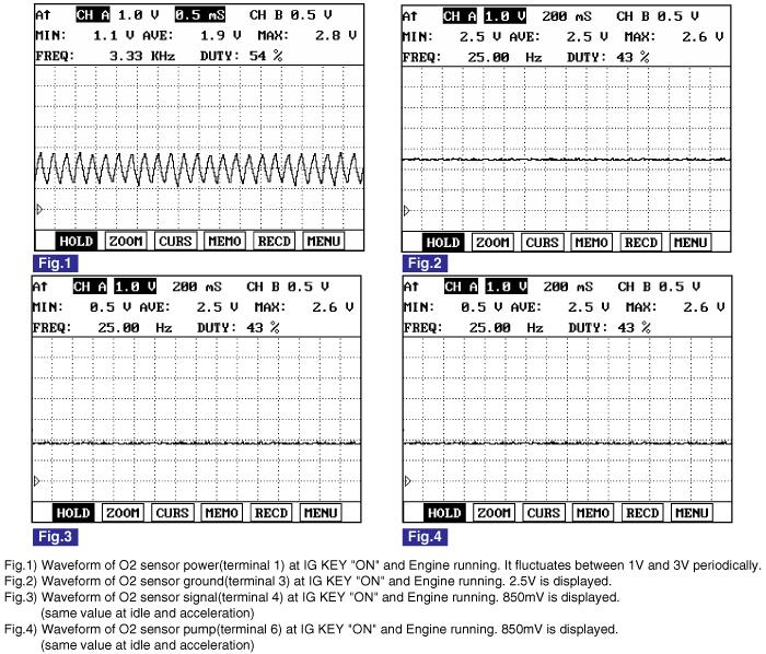
waveform : Refer to "Signal Waveform & Data" of "General Information". The waveform similar to Fig.1) is displayed.

Is the measured voltage within the specification?

▶ Go to "Signal Circuit Inspection".

▶ No voltage detected in O2 sensor power circuit : Go to "2. Check open in sensor power circuit" as follows.
▶ High voltage detected in O2 sensor power circuit : Repair short to battery in O2 sensor power circuit and go to "Verification of Vehicle Repair".
Check open in O2 sensor power circuit
IG KEY "OFF", ENGINE "OFF".
Disconnect O2 sensor connector and ECM connector.
Check continuity between O2 sensor connector terminal 1 and ECM connector terminal 64.
Specification : Continuity(below 1.0Ω )
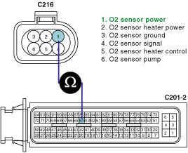
Is the measured voltage within the specification?

▶ Repair short to ground in O2 sensor power circuit and go to "Verification of Vehicle Repair".

▶ Reapir open in O2 sensor power circuit and go to "Verification of Vehicle Repair".
Check voltage in sensor signal circuit
IG KEY "OFF", ENGINE "OFF".
Disconnect O2 sensor connector.
IG KEY "ON".
Measure the voltage of O2 sensor connector terminal 4.
Specification : 0.8V~0.9 V
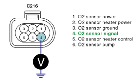
Is the measured voltage within the specification?

▶ Go to "3. Check sensor pump circuit".

▶ No voltage detected in O2 sensor signal circuit : Go to "2. Check open in sensor signal circuit" as follows.
▶ High voltage detected in O2 sensor power circuit : Repair short to battery in O2 sensor signal circuit and go to "Verification of Vehicle Repair".
Check open in O2 sensor signal circuit
IG KEY "OFF", ENGINE "OFF".
Disconnect O2 sensor connector and ECM connector.
Check continuity between O2 sensor connector terminal 4 and ECM connector terminal 87.
Specification : Continuity (below 1.0Ω )
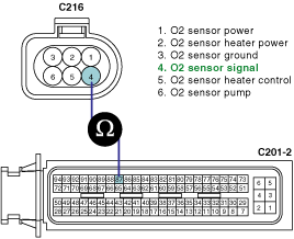
Is the measured resistance within the specification?

▶ Repair short to ground in O2 sensor signal circuit and go to "Verification of Vehicle Repair".

▶ Repair open in O2 sensor signal circuit and go to "Verification of Vehicle Repair".
Check voltage in sensor pump circuit
IG KEY "OFF", ENGINE "OFF".
Disconnect O2 sensor connector.
IG KEY "ON".
Measure the voltage of O2 sensor connector terminal 6.
Specification : 0.8V~0.9 V
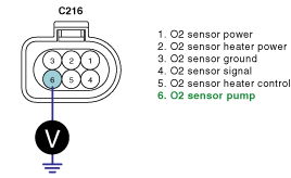
Is the measured voltage within the specification?

▶ Go to "Ground Circuit Inspection".

▶ No voltage detected in O2 sensor pumpl circuit : Go to "4. Check open in sensor pump circuit" as follows.
▶ High voltage detected in O2 sensor power circuit : Repair short to battery in O2 sensor pump circuit and go to "Verification of Vehicle Repair".
Check open in sensor pump circuit
IG KEY "OFF", ENGINE "OFF".
Disconnect O2 sensor connector and ECM connector.
Check continuity between O2 sensor connector terminal 6 and ECM connector terminal 65.
Specification : Continuity (below 1.0Ω )
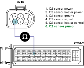
Is the measured resistance within the specification?

▶ Repair short to ground in O2 sensor pump circuit and go to "Verification of Vehicle Repair".

▶ Repair open in O2 sensor pump circuit and go to "Verification of Vehicle Repair".
Check voltage in sensor ground circuit
IG KEY "OFF", ENGINE "OFF".
Disconnect O2 sensor connector.
IG KEY "ON".
Measure the voltage of O2 sensor connector terminal 3.
Specification : 2.3V~2.7V
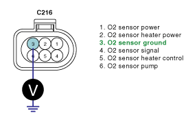
Is the measured voltage within the specification?

▶ Go to"Component Inspection".

▶ No voltage detected in O2 sensor ground circuit : Go to "2. Check open in sensor ground circuit" as follows.
▶ High voltage detected in O2 sensor ground circuit : Repair short to battery in O2 sensor ground circuit and go to "Verification of Vehicle Repair".
Check open in sensor ground circuit
IG KEY "OFF", ENGINE "OFF".
Disconnect O2 sensor connector and ECM connector.
Check continuity between O2 sensor connector terminal 3 and ECM connector terminal 86.
Specification : Continuity (below 1.0Ω )
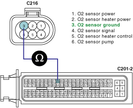
Is the measured resistance within the specification?

▶ Repair short to ground in O2 sensor ground circuit and go to "Verification of Vehicle Repair".

▶ Repair open in O2 sensor ground circuit and go to "Verification of Vehicle Repair".
O2 sensor Visual Inspection
IG KEY "OFF", ENGINE "OFF".
Disconnect O2 sensor connector.
Perform visual inspection for each checking point as follows.
Check corrosion inside of O2 sensor terminal.
Check damaged coverring and open in component wiring.
Check connecting torque(poor connection) of O2 sensor component.
Disconnect O2 sensor and check deformation, clogging, melting of O2 detecting prove.
Specification : Everyting OK
Is any problem of O2 sensor detected?

▶ Replace O2 sensor and go to "Verification of Vehicle Repair".

▶ Refer to "NOTE" as follows.
In diesel engine, ultra lean combustion generates at normal operating condition. Therefore, O2 sensor signal change in accordance with engine acceleration and various loading condition rarely happens, unlikely to linear O2 sensor of gasoline engine. Moreover, pumping current is not measurable with normal measuring device(ampere meter) because maximum value is 3mA. If DTC code is recorded continuously eventhough circuit inspection is correctly performed and no problem at visual inspection of component is detected, replace O2 sensor.
After a repair, it is essential to verify that the fault is corrected.
After connecting Scantool select "DIAGNOSTIC TROUBLE CODES(DTCs)" mode.
Clear recorded DTC using Scantool.
Drive the vehicle within DTC "Enable conditions" in "General information".
After selecting "DIAGNOSTIC TROUBLE CODES(DTCs)" mode and check if DTC is recorded again.
Are any DTCs recorded ?

▶ Go to the DTC guide of recorded NO. in Scantool.

▶ System operates within specification.