If an accidental discharge in the system occurs, ventilate the work area before resuming service.
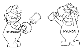
R-134a liquid refrigerant is highly volatile. A drop on the skin of your hand could result in localized frostbite. When handling the refrigerant, be sure to wear gloves.
It is standard practice to wear goggles or glasses to protect your eyes, and gloves to protect your hands. If the refrigerant splashes into your eyes, wash them with clean water immediately.
The R-134a container is highly pressurized. Never leave it in a hot place, and check that the storage temperature is below 52°C (126°F).
A electronic leak detector should be used to check the system for refrigerant leakage. Bear in mind that the R-134a, upon coming into contact with flame, produces phosgene, a highly toxic gas.
Use only recommended the lubricant for R-134a systems. If lubricants other than the recommended one used, system failure may occur.
PAG lubricant absorbs moisture from the atmosphere at a rapid rate, therefore the following precautions must be observed :
When removing refrigerant components from a vehicle, cap immediately the components to prevent from the entry of moisture.
When installing refrigerant components to a vehicle, do not remove the cap until just before connecting the components.
Complete the connection of all refrigerant tubes and hoses without delay to prevent the A/C system from taking on moisture.
Use the recommended lubricant from a sealed container only.
If an accidental discharge in the system occurs, ventilate the work area before resuming service.

Never open or loosen a connection before discharging the system.
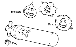
Seal the open fittings of components with a cap or plug immediately to preventintrusion of moisture or dust.
Do not remove the sealing caps from a replacement component until it is ready to be installed.
Before connecting an open fitting, always install a new sealing ring. Coat the fitting and seal with refrigerant oil before making the connection.
BOLT/NUT COUPLING TYPE
Lubricate each connecting parts with compressor oil so as to tighten them easily, enough to prevent refrigerant leaks.
Use two wrenches not to twist the tube.
Tighten them to the specified torque.
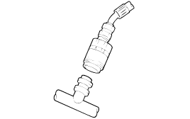
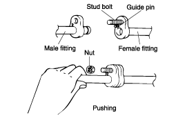
FLANGE WITH GUIDE PIN TYPE
Check the O-ring for missing and damage, then lubricate it with compressor oil.
Push the pipe as shown in the illustration and tighten the nub by hand.
Tighten the nut to the specified torque.
The oil used to lubricate the compressor circulates in the system while the compressor is operating. Whenever replacing any component of the system or when a large amount of gas leakage occurs, add oil to maintain the original total amount of oil.
Single : 140 - 160g
HANDLING OF OIL
The oil should be free from moisture, dust, metal filings, etc.
Do not mix oils.
The moisture content in the oil increases when exposed to air for prolonged periods. After use, seal the container immediately.
OIL RETURN OPERATION
To check the oil level or add oil, idle engine for 20~30 minutes and setting the heater control set to maximum cooling and blower level, to return the lubricant to compressor.
CHECKING AND ADDING COMPRESSOR OIL
In order to add oil to an operating compressor, check the compressor oil using the following procedure:
Perform the oil return operation, stop the engine, discharge the refrigerant, and dismantle the compressor from vehicle.
Discharge oil from the system line outlet.
If compressor is cold, sometimes it can be hard to drain the oil. Warm up the compressor (approx. 40~50°C) to drain the oil.
Check the amount of the discharged oil. If it is less than 70cc, it means there is a little leak of oil. Perform the leakage test on each system connection, and repair or replace faulty parts if necessary.
Check oil for contamination and set the oil level in the following procedure:
Discharge | Setting |
Above 70cc | Oil level is normal, add equal amount of discharged oil. |
Below 70cc | Oil level is low add 70cc of oil. |
ADDING OIL FOR REPLACEMENT PARTS
When replacing the system's component parts, be sure to add the following amount oil to the parts being replaced.
Replacement parts | Oil quantity |
Evaporator core | 90 |
Condenser | 90 |
When connecting the manifold gauge set, be sure to observe all safety precautions.
Close both hand valves of the manifold gauge fittings.
Install the charging hoses of the gauge set to the fittings. Connect the low-pressure hose to the low-pressure service port, and the high-pressure hose to the high-pressure service port. Tighten the hose nuts by hand.
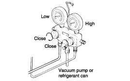
When charging the refrigerant, do it after removing the engine cover and the air intake hose.
Connect the manifold gauge set to the system.
Put a towel under the open end of the center hose.
Open the high pressure valve slowly to discharge the refrigerant.
If discharging the refrigerant too fast, compressor oil may drain from the system.
Check if the towel is stained with oil. If so, gently close the valve.
If the manifold gauge reading drops below 3.5kg·cm², open the low pressure valve slowly.
Open the high and low pressure valves slowly in order to drop the system pressureuntil the gauge indicates 0kg·cm².
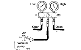
It is necessary to evacuate the air conditioning system any time the system has been opened. Evacuation is necessary to rid the system of all air and moisture that may have been allowed to enter the unit. After installation of a component, the system should be evacuated for approximately 15 minutes. A component in service that has been opened for repair should be evacuated for 30 minutes.
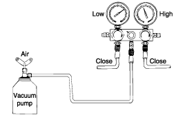
Engine should be off.
Connect a manifold gauge set to the compressor gauge fittings. Close both high and low pressure valves.
Make sure the refrigerant has been discharged from the system.
Connect the center hose of the gauge set to the vacuum pump inlet.
Start the vacuum pump and then open the high and low manifold pressure valves.
After about ten minutes, check that the low pressure gauge reads more than 94,39 kPa (0.96 kg·cm², 13.7 psi) of vacuum. If negative pressure can not be obtained, there is a leak in the system. In this case, repair the leak as follows:
Close both manifold valves and stop the vacuum pump.
Charge the system with a can of refrigerant [about 0.4 kg (0.9 lb)]. Refer to Charging Refrigerant.
Check for refrigerant leakage with a leak detector. Repair any leakage found. Refer to Checking Refrigerant Leak.
Discharge refrigerant again, and then evacuate the system. If no leaks are found, continue evacuating the system.
Start the vacuum pump.
Open both manifold pressure valves to obtain 94.39 kPa (0.96 kg·cm², 13.7 psi) of vacuum.
After the low pressure manifold gauge indicates close to 94.39 kPa (0.96 kg·cm², 13.7 psi), continue evacuating for 15 minutes.
After evacuating for 15 minutes, close both manifold pressure valves and stop the vacuum pump. Disconnect the hose from the vacuum pump. The system is now ready for charging.

Before connecting the valve to the refrigerant container, turn the handle fully counterclockwise.
Turn the disc counterclockwise until it reaches its highest position.
Connect the center hose to the valve fitting. Turn the disc fully clockwise by hand.
Turn the handle clockwise to make a hole in the sealed top.
Loosen the center hose nut connected to the center fitting of the manifold gauge.
Allow air to escape for a few seconds, and then tighten the nut.
This step is to charge the system through the low pressure side with the refrigerant in a vapor state. When the refrigerant container is placed upright, refrigerant will enter the system as a vapor.

Install the refrigerant can tap valve as described in Handling the Refrigerant Tap Valve section.
Open the low pressure valve. Adjust the valve so that the low pressure gauge does not read over 412 kPa (4.2 kg·cm², 60 psi).
Put the refrigerant in a pan of warm water (about 40°C or 104°F) to keep vapor pressure in the container slightly higher than vapor pressure in the system.
Run the engine at fast idle and operate the air conditioning.
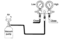
Be sure to keep the container upright to prevent liquid refrigerant from being charged into the system through the suction side, resulting in possible damage to the compressor.
Charge the system to the specified amount. Then close the low pressure valve.
Specified amount : 500±25g
When refrigerant charging speed is slow, immerse the refrigerant can in heated water. (a temperature of approx. 40°C (104°F)).
Under any circumstances, the refrigerant must not be warmed in water heated to a temperature of over 52°C (126°F).
A blow torch or stove must never be used to warm up the can.
This step is to charge an empty system through the high pressure side with refrigerant in a liquid state. When the refrigerant container is held upside down, refrigerant will enter the system as a liquid.
Never run the engine when charging the system through the high pressure side. Do not open the low pressure valve when the system is being charged with liquid refrigerant.
Close both high and low pressure valves completely after the system is evacuated.
Install the refrigerant can tap valve as described in "Handling the Refrigerant Service Tap Valve" section.
Open the high pressure valve fully and keep the container upside down.
Charge the system to the specified amount by weighing the refrigerant with a scale. Overcharging will cause discharge pressure (high side) to rise. Then, close the high pressure valve.
Specified amount : 500±25g
After the specified amount of refrigerant has been charged into the system, close the manifold gauge valve.
Confirm that there are no leaks in the system by checking with a leak detector. Refer to Checking for Refrigerant Leak.
Conducting a performance test prior to removing the manifold gauge is good service practice.
Always conduct a leak test with an electronic leak detector whenever leakage or refrigerant is suspected and when conducting service operations which are accompanied by disassembly or loosening or connection fittings.
Check the torque on the connection fittings and, if too loose, tighten to the proper torque. Check for gas leakage with a leak detector.
If leakage continues even after the fitting has been tightened, discharge the refrigerant from the system, disconnect the fittings, and check their seating faces for damage. Always replace, even if the damage is slight.
Check the compressor oil and add oil if required.
Charge the system and recheck for gas leaks. If no leaks are found, evacuate and charge the system again.
Item | Deflection (mm) |
New one | 5~5.5 |
Used one | 6~7 |
After driving | 8 |
Install the manifold gauge set.
Run the engine at 2,000 rpm and set the controls for maximum cooling and high blower speed.
Keep all windows and doors open.
Place a dry-bulb thermometer in the cool air outlet.
Place a psychrometer close to the inlet of the cooling unit.
Check that the reading on the high pressure gauge is 1,373-1,575 kPa (14-16kg·cm², 199-228 psi). If the reading is too high, pour water on the condenser. If the reading to too low, cover the front of the condenser.
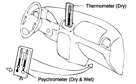
Check that the reading on the dry-bulb thermometer at the air inlet is 25~35°C (77~95°F).
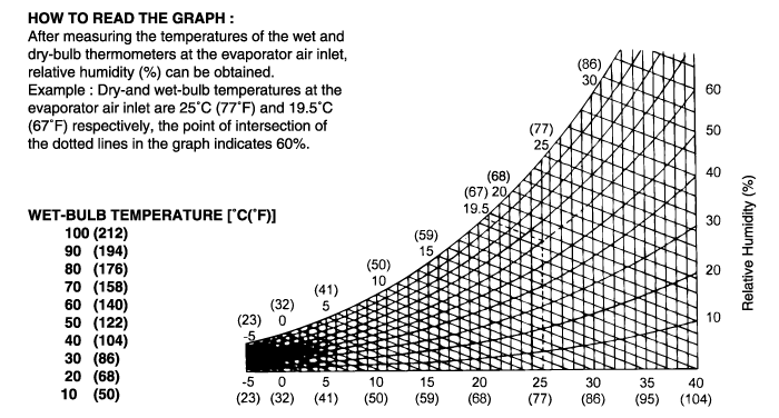
Calculate the relative humidity from the psychrometric graph by comparing the wet-and dry-bulb reading of the psychrometer at the air inlet.
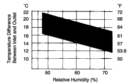
Measure the dry-bulb temperature at the cool air outlet, and calculate the difference between the inlet dry-bulb and outlet dry-bulb temperatures.
Check that the intersection of the relative humidity and temperature difference is within the block hard line. If the intersection is within the block hard line, cooling performance is satisfactory.
