2.
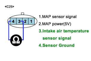
Probe(+) : IATS signal circuit NO4
Probe(-) : IATS ground circuit NO3
a.
Specification: 20℃(68℉) : 2.27~2.64㏀ ,80℃(176℉) : 0.30~0.33㏀
Measuring the resistence of IAT is to find whether the open circuit exists in the sensor’s inner side.
Measure resistance of IATS signal circuit between ground circuit.
Probe(+) : IATS signal circuit NO4
Probe(-) : IATS ground circuit NO3
Specification: 20℃(68℉) : 2.27~2.64㏀ ,80℃(176℉) : 0.30~0.33㏀
Does each resistance indicate continuity circuit?
YES
Go to "ECM Inspection"
NO
Open circuit IATS
Repair as necessary and go to "Verification of Vehicle Repair" procedure
The purpose to measure IAT resistence is to decide where open circuit exists and the method is to check continuity between IAT signal line and ground line.
The purpose of checking ECM is to determine whether there is any malfunction of ECM .IATS sensor connect and Turn ignition switch to ON.
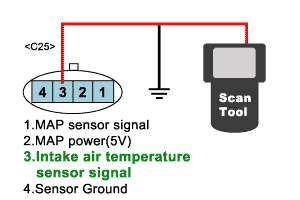
IATS sensor connect and Turn ignition switch to ON.
Probe(+) : IATS sensor harness connector NO3.
Probe(-) : Chassis ground.
Verify IATS voltage to change while raising or lowering simulation voltage with scan tool within 0.5~3.5 V.
Specification: If the data is changeable as simulation voltage changes,it’s OK.
Is Temperature data changeable Specification?
YES
Temporarily install a known good IATS and check for proper operation.
If problem is corrected, replace IATS.
NO
ECM internal faulty.
Repair as necessary and go to "Verification of Vehicle Repair" procedure.
