1.
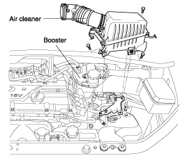
Remove the air cleaner.
Be careful not to bend or damage the brake lines when removing the master cylinder.
Do not spill brake fluid on the vehicle; it may damage the paint; if brake fluid does contact the paint, wash it off immediately with water.
To prevent spills, cover the hose joints with rags or shop towels.
Remove the air cleaner.
Remove the brake fluid level switch connector.
After removing the brake reservoir cap, suck out the brake fluid in the reservoir using a syringe or equivalent.
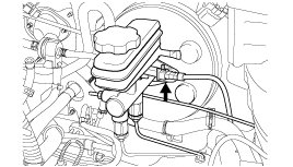
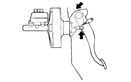
Disconnect the brake tube from the master cylinder.
Take care not to contaminate the brake fluid by other parts.
Remove the master cylinder from the brake booster.
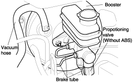
Remove the vacuum hose from the booster.
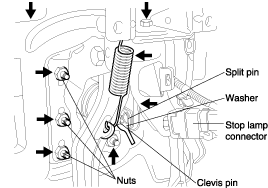
Remove the push rod from the brake pedal.
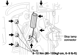
Remove the booster mounting nuts.
Install the brake booster and tighten mounting nut.
Tightening torque Nm (kgf·cm, lb·ft)
Brake booster mounting nut : 8~12 (80~120, 6~9)
Apply grease to the contact points of the brake pedal and the push rod.
Connect the brake pedal and the clevis with a clevis pin and install the split pin to the clevis pin.
After installing the master cylinder, install the brake tube to the master cylinder.
Connect the vacuum hose to the brake booster.
Make sure that there are no bend, twist, or leaks in the vacuum hose.
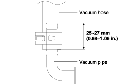
When installing the vacuum hose to the vacuum pipe, the vacuum pipe should be inserted to the depth of 25~27mm (0.98~1.06 in.) as shown in the illustration.
Fill the brake reservoir with brake fluid, and bleed the system. (Refer to "Air bleeding" in adjustment procedure)
Check for brake fluid leaks.
Inspect and adjust the brake pedal. (Refer to "Brake pedal height adjustment" in adjustment procedure)
After installation, apply grease to the contact points of the clevis and brake pedal sufficiently.
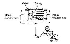
When checking the check valve, keep the check valve fit in the vacuum hose.
Remove the vacuum hose.
The check valve is press-fitted inside the vacuum hose at the position of the marking.
Check the operation of the check valve by using a vacuum pump.
Vacuum pump connection | Accept/Reject criteria |
Connection at the brake booster side (A) | A negative pressure (vacuum) is created and held |
Connection at the brake booster side (B) | A negative pressure (vacuum) is not created |
If the check valve is defective, replace it if an assembly unit together with the vacuum hose.