3.
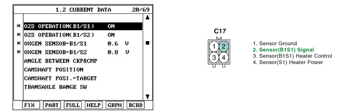
Monitor "HO2S(B1S1)" parameter on scantool.
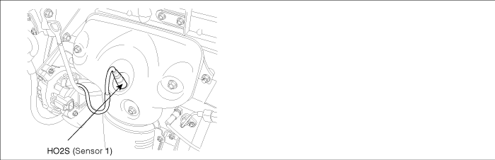
In order to control emissions of the CO, HC and NOx components of the exhaust gas, heated oxygen sensor (HO2S), mounted on the front side and rear side of catalytic converter, detects the oxygen content in the exhaust gas. The front HO2S signal is used to control air/fuel ratio (closed loop fuel control) and the rear HO2S signal is used to monitor front HO2S and catalyst for proper operation.
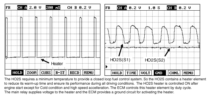
The HO2S requires a minimum temperature to operate properly and provide a closed loop fuel control system. The HO2S contains the heater element to reduce its warming-up time and ensure its performance during all driving conditions.The ECM controls this heater element by duty cycle. The main relay supplies voltage to the heater and the ECM provides a ground circuit for activating the heater.
When ECM detects open or short to ground in the heater control circuit(B1S1), ECM sets DTC P0031.
Item | Detecting Condition | Possible Cause |
DTC Strategy | ● Check voltage | ● Poor connection ● Open or short to ground in power circuit ● Open or short to ground in control circuit ● B1S1 ● ECM |
Enable Conditions | ||
Threshold Value | ● Open or short to ground | |
Diagnostic Time | ● Continuous | |
MIL | ● ON |
※ B1S1 : upstream oxygen sensor / B1S2 : downstream oxygen sensor
ITEM | Specification |
Heater Resistance(Ω) | Approx. 9.0Ω(20℃) |
Connect scantool to DLC (Data Link Cable).
Warm up the engine to normal operating temperature.
Monitor "HO2S(B1S1)" parameter on scantool.
Is the "HO2S(B1S1)" parameter operating correctly?

▶ Fault is intermittent caused by poor contact in the sensor's and/or ECM's connector or was repaired and ECM memory was not cleared. Thoroughly check connectors for looseness, poorconnection, ending, corrosion, contamination, deterioration, or damage. Repair or replace asnecessary and go to "Verification of Vehicle Repair" procedure.

▶ Go to "Terminal and Connector Inspection" procedure.
Many malfunctions in the electrical system are caused by poor harness and terminals. Faults can also be caused by interference from other electrical systems, and mechanical or chemical damage.
Thoroughly check connectors for looseness, poor connection, bending, corrosion, contamination, deterioration, or damage.
Has a problem been found?
▶ Repair as necessary and go to "Verification of vehicle Repair" procedure.
▶ Go to "Power Circuit Inspection" procedure.
IG "OFF".
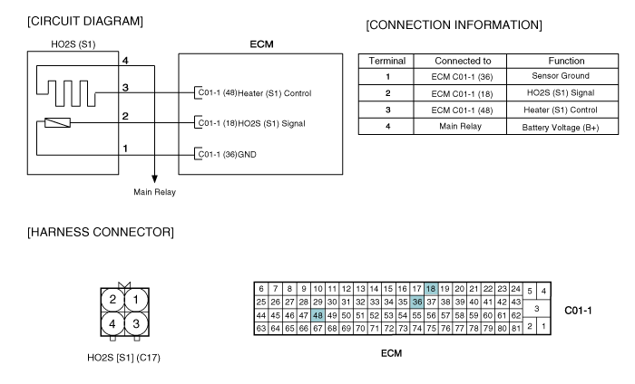
Disconnect HO2S(S1) connector.
IG "ON" & ENG "OFF"
Measure voltage between terminal 4 of HO2S(S1) harness connector and chassis ground.
Specification : B+
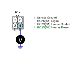
Is the measured voltage within specification?
▶ Go to "Control Circuit Inspection" procedure.
▶ Repair or replace as necessary and then, go to "Verification of Vehicle Repair" procedue.
IG "OFF".
Disconnect HO2S(S1) connector.
IG "ON" & ENG "OFF"
Measure voltage between terminal 3 of HO2S(S1) harness connector and chassis ground.
Specification : Approx. 3.5V
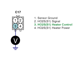
Is the measured voltage within specification?
▶ Go to "Component Inspection" procedure.
▶ Repair or replace as necessary and then, go to "Verification of Vehicle Repair"procedure.
Check resistance.
IG "OFF".
Disconnect HO2S(S1) connector.
Measure resistance between terminal 3 and 4 of HO2S(S1)(Component Side)
ITEM | Specification |
Heater Resistance(Ω) | Approx. 9.0Ω(20℃) |
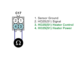
Is the measured resistance within specification?
▶ Substitute with a known - good ECM and check for proper operation.
▶ If the problem is corrected, replace ECM and go to "Verification of Vehicle Repair" procedure.
▶ Substitute with a known - good HO2S(S1) and check for proper operation.
▶ If the problem is corrected, replace HO2S(S1) and go to "Verification of Vehicle Repair" procedure.
After a repair, it is essential to verify that the fault has been corrected.
Connect scan tool and select "Diagnostic Trouble Codes(DTCs)" mode.
Clear the DTCs and Operate the vehicle within DTC Enable conditions in General information.
Are any DTCs present ?
▶ Go to the applicable troubleshooting procedure.
▶ System is performing to specification at this time.
