4.
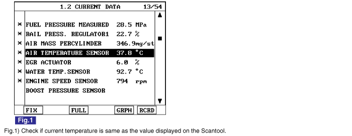
Monitor "AIR TEMPERATURE SENSOR" parameter on the Scantool.
specification : current intake air temperture is displayed.

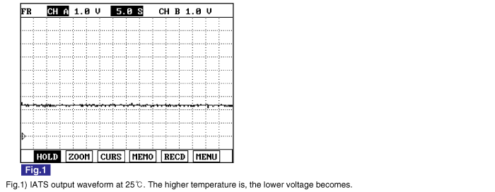
Intake Air Temperature Sensor(IATS) is NTC thermistor. Installed inside of both AFS and BPS, it senses intake air temperature. In case of EURO-4 diesel engine, IATS is installed in front of turbocharger(inside of AFS) and behind it(inside of BPS). Comparing air temperature from both sensors(one is intake air temperature, the other is air temperature passing through turbo charger), more accurate sensing of intake air temperature is possible.With intake air temperature signal, ECM performs EGR control correction and fuel injection quantity correction.(AFS is needed for EGR FEED BACK control in electronically controlled diesel engine. The calculation of air density at certain temperture is required to perform EGR FEED BACK control correctly.)
P0098 is set when the voltage above 4965mV - maximum output voltage of IATS(integrated with BPS) - is detected for more than 2.0 sec.. This code is due to 1) open or 2) short to ground or 3) short to battery in IATS signal circuit.
Item | Detecting Condition | Possible Cause | ||
DTC Strategy | ● Voltage monitoring | ● IATS circuit ● IATS component | ||
Enable Conditions | ● IG KEY "ON" | |||
ThresholdValue | ● Output signal above maximum value( above 4965mV ) | |||
DiagnosticTime | ● 2.0 sec. | |||
Fail Safe | Fuel Cut | NO | ||
EGR Off | NO | |||
Fuel Limit | NO | |||
MIL | NO | |||
Temp. | -40℃ | -20℃ | 0℃ | 20℃ | 40℃ | 60℃ | 80℃ |
Resistance | 35.14~43.76KΩ | 12.66~15.12KΩ | 5.12~5.89KΩ | 2.29~2.55KΩ | 1.10~1.24KΩ | 0.57~0.65KΩ | 0.31~0.37KΩ |
Connect Scantool to Data Link Connector (DLC).
Warm engine up to normal operating temperature.
Turn "OFF" electrical devices and A/C.
Monitor "AIR TEMPERATURE SENSOR" parameter on the Scantool.
specification : current intake air temperture is displayed.
Electrical systems consist of a lot of harness and connectors, poor connection of terminals can cause various problems and damge of component.
Perform checking procedure as follows.
Check damage of harness and terminals : Check terminals for contact resistance, corrosion and deformation.
Check connecting condition of ECM and component connector : Check terminal seperation, damage of locking device and connecting condition between terminal and wiring.
Disconnect the pin which requires checking at male connector and insert it to the terminal at female connector for checking connecting condition. ( after checking, reconnect the pin at correct position. )
Is the problem found?

▶ Repair the trouble causing part and go to "Verification of Vehicle Repair".

▶ Go to "Signal Circuit Inspection".
Check signal circuit voltage
IG KEY "OFF", ENGINE "OFF".
Disconnect BPS connector.
IG KEY "ON"
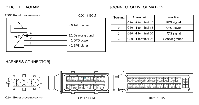
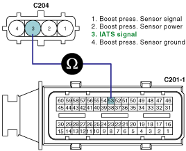
Check the voltage of BPS connector terminal 3.
Specification : 4.8V~5.1V
Is the measured voltage within the specificaiton?
▶ Go to "Ground Circuit Inspection".
▶ Go to "2.Check open in signal circuit" as follows.
Check open in signal circuit
IG KEY "OFF", ENGINE "OFF".
Disconnect BPS connector and ECM connector.
Check continuity between BPS connector terminal 3 and ECM connector terminal 53.
Specification : Continuity (below 1.0Ω )
Is the measured resistance within the specification?
▶ Go to "3. Check short to battery in signal circuit" as follows.
▶ Repair open in signal circuit and go to "Verification of Vehicle Repair".
Check short to battery in signal circuit
IG KEY "OFF", ENGINE "OFF".
Disconnect BPS connector and ECM connector.
IG KEY "ON"
Check the voltage of BPS connector terminal 3.
Specification : 0.0V~0.1V
Is the measured voltage within the specification?(with both connector disconnected)
▶ Repair short to battery in signal circuit and go to "Verification of Vehicle Repair".
▶ Go to "Ground Circuit Inspection".
IG KEY "OFF", ENGINE "OFF".
Disconnect BPS connector.
IG KEY "ON".
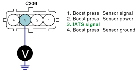
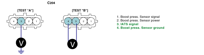
Measure the voltage of BPS connector terminal 3. [ TEST "A" ]
Measure the voltage between BPS connector terminal 3 and 4. [ TEST "B" ]
( terminal 3 : Check + prove , terminal 4 : Check - prove )
Specification : [TEST "A"] Voltage - [TEST "B"] Voltage = below 200mV
Is the measured voltage within the specification?
▶ Go to "Component Inspection".
▶ When "B" voltage is not detected : Repair open in ground circuit and go to "Verification of Vehicle Repair".
▶ When the voltage difference between "A" and "B" is above 200mV : Eliminate the causes of excessive resistance and go to "Verification of Vehicle Repair".
IG KEY "OFF", ENGINE "OFF".
Disconnect BPS connector.
Measure resistance between IATS component terminal 3 and 4, referring to resistance characteristic table of specification of General information.
Specification : Refer to Specification of General Information
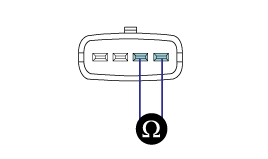
Is the measured resistance at certain temperature within the specified resisance range at the temperature?
▶ Go to "Verification of Vehicle Repair".
▶ Replace BPS assy' and go to "Verification of Vehicle Repair".
After a repair, it is essential to verify that the fault is corrected.
After connecting Scantool select "DIAGNOSTIC TROUBLE CODES(DTCs)" mode.
Clear recorded DTC using Scantool.
Drive the vehicle within DTC "Enable conditions" in "General information".
After selecting "DIAGNOSTIC TROUBLE CODES(DTCs)" mode and check if DTC is recorded again.
Are any DTCs recorded ?
▶ Go to the DTC guide of recorded NO. in Scantool.
▶ System operates within specification.
