Check the contact surface on the cam and vlave stem.
If badly worn or damaged, replace it.

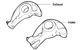
Check the rocker face.
Replace it if damaged or pressed.
Check the contact surface on the cam and vlave stem.
If badly worn or damaged, replace it.

Check hydraulic lash adjust (HLA) face that contact the valve stem if badly worn or damaged, replace the HLA. (1.3 only)

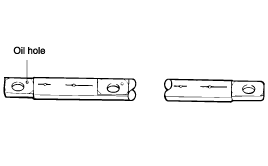
Check the rocker arm shafts for damage. Replace as necessary.
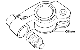
Check the oil hole whether clogged or not.

Problem | Possible cause | Action |
● Temporary noise on startin a cold engine | Normal | This noise will disappear after the oil in the engine has reached normal pressure. |
● Continuous noise when engine is started after loger than 48 hours parking. | Oil drain out of the high pressure chamber on HLA, allowing air to get in. | Noise will disappear within 15 minutes when engine run at 2000~3000 rpm If not disappear, refer to item 7 below |
● Continuous noise when engine is first started after rebuilding cylinder head. | Insuffecient oil in cylinder head oil gallery. | |
● Continuous noise when engine is after excessive craking the engine by starter motor or band. | Oil drain out of the high-pressure chamber in HLA, allowing air to get in. | |
● Continuous noise when engine is after changing HLA. | caution Do not run engine all a speed higher than 3000 rpm as this may damage HLA. | |
● Continuous noise during idle after high speed running. | Engine oil level too high or too low. | Check oil level. Drain or add oil as necessary. |
Execssive amount of air in the oil at high engine speed. | Check oil supply system | |
Deteriorated oil | Check oil quality. If deteriorated, replace with specified type and amount of oil. | |
● Noise cotinues more than 15 minutes. | Low oil pressure | Check oil pressure and oil supply system of each part of engine. |
Faulty HLA. | Remove the cylinder head over and press down HLA by band. If it moves, replace HLA. caution Be careful of hot HLA. |
Warm up engine.
Remove the rocker cover.
Turn crankshaft to nomal direction (right turn at engine front view) stop it at No.1 compression top dead center, shown in fig. Valve clearance adjustable at No.1 compression top dead center.
CYLINDER NO. | 1 | 2 | 3 | 4 |
INTAKE | ○ | ○ | ||
EXHAUST | ○ | ○ |
Insert clearance gauge between rocker arm adjusting screw and vlave stem end.
Then fix screw with lock nut after adjusting valve clearance.
INTAKE | EXHAUST | |
Standard Clearance (Warm) | 0.2 mm | 0.25 mm |
Reference Clearance (Cold) | 0.1 mm | 0.17 mm |
Turn crankshaft just one revorution to nomal direction (right turn at engine front view) stop it at No. 4 compression top dead center.
Insert clearance gauge between rocker arm adjusting screw and vlave stem end.
Them fix screw with lock nut after adjusting valve clearance.
Valve clearance adjustable at No. 4 compression top dead center.
CYLINDER NO. | 1 | 2 | 3 | 4 |
INTAKE | ○ | ○ | ||
EXHAUST | ○ | ○ |