2.
Probe(+) : TPS harness terminal 1
Probe(-) : Chassis ground.
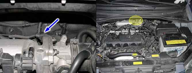
Throttle Position (TP) Sensor measures the opening angle of throttle valve and mounts on the side of the throttle body and is connected to the throttle blade shaft. The TP sensor’s resistance changes according to the throttle blade shaft position. TP Sensor has a potentiometer whose resistance changes along with the Throttle valve position. The Powertrain Control Module (PCM) provides a 5volt reference voltage to the TP Sensor. The PCM reads the voltage across the TP Sensor and converts it into throttle position. During acceleration, the TP Sensor resistance decreases. During deceleration, the TP Sensor resistance increases. The PCM uses the TP Sensor signal to adjust timing and injector pulse width. The TP Sensor signal along with the MAF sensor signal is used by the PCM to calculate engine load. Throttle angle information to the PCM to be used for the detection of engine status such as idle, part load, full throttle and acceleration fuel enrichment .
The ECM sets DTC P0122 if the ECM detects signal voltage lower than the possible range of a properly operating TPS.
Item | Detecting Condition | Possible cause |
DTC Strategy | ● Signal check, low | ● Open in power line. ● Open circuit between signal and ground line. ● Bad TPS. ● Bad ECM. |
Threshold value | ● Throttle poening degree : < 3.14%(0157V) | |
Enable Conditions | ● Engine speed : > 600rpm | |
Diagnostic Time | ||
MIL on condition | ● 0 . 08sec |
Service standard
Idle : 0%(250~850mV)
Gradually open : Inccreases
Open fully : 75~85%(4000~4800mV)
Service standard
Idle : 0%(250~850mV)
Gradually open : Increases
Open fully : 75~85%(4000~4800mV)
Start engine and warm up to operating temperature.
Probe(+) : TPS harness terminal 1
Probe(-) : Chassis ground.
It is normal that the output of TPS changes in accordance with that of MAP sensor.
In case there is no symptom and wrong data but DTC is shown
The problem may be intermittent so slightly shake the connector and harness vertically and horizontally to check if there is any data changes
If the data changes normally, the problem was intermittent so erase DTC and verify the same DTC reoccure.
Go to "Terminal and Connector inspection" procedure.
In case there is symptom and wrong data with DTC
Check open,short or connector’s connection for TPS.
Check the deterioration of TPS performance.
Go to "Circuit Inspection" procedure.
When checking TPS waveform,it is strongly recommended to examine waveform with MAP sensor waveform.
Periode ① Is the voltage of MAP in idling and 0.8~1.2 V,and there must be a little fluctuation in waveform.
In case there is no fluctuation
Possible cause : Deteriorated MAP sensor or some foreign material in TPS sensor.
The voltage in Periode ② Is 0.3~1.0V in average.
Periode ③ Is in W.O.T and the voltage there is 4.3 V, and MAP sensor voltage is about 4.3 V.