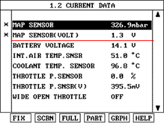
Check for MAP sensor signal at idle.

The data shown above is only for reference and there may be a little difference actually.
It is normal that the output of MAP sensor changes in accordance with TPS angle.
This is the inspection procedure to determine whether it is present DTC or memoried one by monitoring the current signal or by using the function of oscilloscope with Hi-scan pro.
Connect scan tool to DLC.
IG KEY : ON
Start engine and warm up to operating temperature.
Check for MAP sensor signal at idle.

The data shown above is only for reference and there may be a little difference actually.
It is normal that the output of MAP sensor changes in accordance with TPS angle.
This inspection procedure is recommended when service data with scan tool in not enough.
Start engine and warm up to operating temperature.
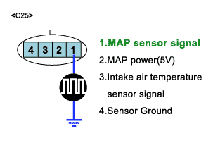
Probe(+) : MAP sensor harness connector NO1.
Probe(-) : Chassis ground.

It is normal that the output of MAP sensor changes in accordance with TPS angle.
Ignition ON and engine OFF.
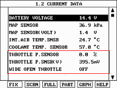
Using SCAN TOOL, monitor TPS voltage signals while slowly opening the throttle.
SCAN-TOOL : Sensor output

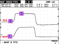
When checking TPS waveform,it is strongly recommended to examine waveform with MAP sensor waveform.
Peride ① is the voltage of MAP in idling and 0.8~1.2 V,and there must be a little fluctuation in fform.
In case there is no fluctuation
Possible cause : Deteriorated MAP sensor or some foreign material in MAP sensor.
The voltage in Periode ② is 0.3~1.0V in average.
Periode ③ is in W.O.T and the voltage there is 4.3 V,and MAP sensor voltage is about 4.3 V.

In case there is no symptom and wrong data but DTC is shown
In case there is no symptom and wrong data but DTC is shown
The problem may be intermittent so slightly shake the connector and harness vertically and horizontally to check if there is any data changes
If the data changes normally, the problem was intermittent so erase DTC and verify the same DTC reoccure.
Go to "Terminal and Connector inspection" procedure.
In case there is symptom and wrong data with DTC
Check open,short or connector’s connection for MAP.
Check the deterioration of MAP performance.
Go to "Visual/Physical inspection" procedure.
When checking TPS waveform,it is strongly recommended to examine waveform with MAP sensor waveform.
Peride ① is the voltage of MAP in idling and 0.8~1.2 V,and there must be a little fluctuation in fform.
In case there is no fluctuationf
Possible cause : Deteriorated MAP sensor or some foreign material in MAP sensor.
The voltage in Periode ② is 0.3~1.0V in average.
Periode ③ is in W.O.T and the voltage there is 4.3 V,and MAP sensor voltage is about 4.3 V.
