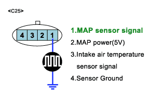
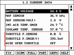
Terminal and Connector Inspection
1.

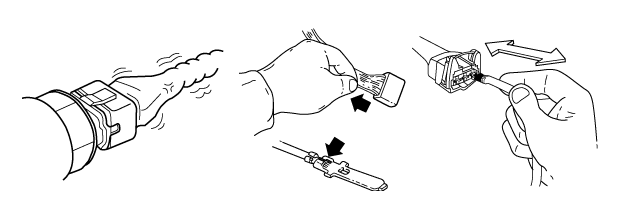
Many malfunctions in the electrical system are caused by poor harness(s) and terminals. Faults can also be caused by interference from other electrical systems, and mechanical or chemical damage.

2.

Check the following conditions:

(1)

Check for damaged harness and terminals: contact resistance, oxidation, bent or broken terminals.

(2)

Check for poor connection between ECM and component: backed out terminal, improper mating, broken locks or poor terminal to wire connection

caution

Use a suitable male pin to ensure that contact in sockets is good. The pin should remain in position when pulled gently.
3.

Has a problem been found?

YES

a.

Repair as necessary and go to "Verification of Vehicle Repair" procedure

NO

a.

System OK. Go to "Verification of Vehicle Repair" procedure

Visual / Physical Inspection

When checking MAP sensor visual inspection is necessary.

1.

Thoroughly check MAP for loose, poor connection, bent, corrosion, contamination, deterioration,or damage.

a.

Is MAPS OK?

YES

Go to "Monitor Scantool data TPS"

NO

Clean or Repair as necessary and go to "Verification of Vehicle Repair"

Instake System Inspection
1.

Check air cleaner for dirt, blockage, or damage.

2.

Check entire air intake system for leaks or blockages such as :

▶ Throttle body

▶ PCV valve

▶ Intake manifold

▶ Gasket beween intake manifold and surge tank

▶ Seals beween intake manifold and fule injectors

▶ Seal beween surge tank and PCV pipe

a.

Is entire air intake system okay?

YES

Temporarily install a known good MAP and check for proper operatiuon.

if problem is corrected, replace MAP.

NO

Repair or replace as necessary and go to "Verification of Vehicle Repair"

Monitor Scantool Data

This is the inspection procedure to determine whether it is present DTC or memoried one by monitoring the current signal or by using the function of oscilloscope with Hi-scan pro.

Inspection of Sensor Output
1.

Connect scan tool to DLC.

2.

IG KEY : ON

3.

Start engine and warm up to operating temperature.

4.

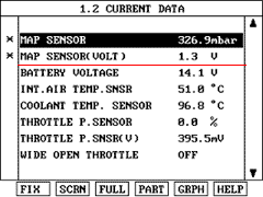
Check for MAP sensor signal at idle.

caution

The data shown above is only for reference and there may be a little difference actually.

It is normal that the output of MAP sensor changes in accordance with TPS angle.

Waveform Inspection in Oscilloscope Mode

This inspection procedure is recommended when service data with scan tool in not enough.

5.

Start engine and warm up to operating temperature.

6.

Probe(+) : MAP sensor harness connector NO1.

Probe(-) : Chassis ground.

caution

It is normal that the output of MAP sensor changes in accordance with TPS angle.

Monitor Scantool Data
1.

Ignition ON and engine OFF.

2.

Using SCAN TOOL, monitor TPS voltage signals while slowly opening the throttle.

3.

SCAN-TOOL : Sensor output

Яндекс.Метрика