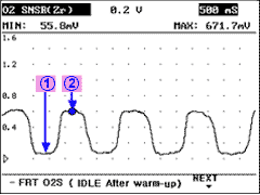
In case the duration ② is longer than the duration ①
Possible cause : Injector leakage,high fuel pressure,faulty MAP sensor faulty ECTS.

In order to provide the best possible combination of drivability, fuel economy and emission control, the ECM uses a closed loop air/fuel metering system. The ECM monitors the HO2S signal voltage and adjusts fuel delivery based it in closed loop fuel control. Changes in fuel delivery will be indicated by the long-term and the short-term fuel trim values. The ideal fuel trim value is around 0%. The ECM will add fuel when the HO2S signal is indicating a lean condition. Additional fuel is indicated by fuel trim values that are above 0%. The ECM will reduce fuel when the HO2S signal is indicating a rich condition. Reduction in fuel is indicated by fuel trim values that are below 0%. The DTC relevant to fuel trim will be set when the amount reaches excessive levels because of a lean or rich condition.
The ECM sets DTC P0171 if long-term and short-term value are higher than the threshold value.
Item | Detecting Condition | Possible cause |
Monitoring Strategy | ● Feul trim limits exceeded, too lean | ● Faulty fuel delivery system. ● Clogged fuel injectors. ● Faulty fuel injectors. ● Leak in intake system. ● Leak in exhaust system. ● Faulty MAP. ● Faulty TPS. ● Faulty front HO2S. |
Threshold value | ● Additive long term value > 8.5% | |
● Multiplicative long term value 1 > 1.23 | ||
● Multiplicative long term value 2 > 1.23 | ||
Enable Conditions | ● Air mass ≤ 18kg/h | |
● Air mass 30∼105kg/h | ||
● Air mass ≥ 140kg/h | ||
Diagnostic Time | ● 25 sec Continuous | |
MIL on condition | ● 2 driving cycle |
- Faulty fuel delivery system.
- Clogged fuel injectors.
- Faulty fuel injectors.
- Leak in intake system.
- Leak in exhaust system.
- Faulty MAP.
- Faulty TPS.
- Faulty front HO2S.
2500 rpm : Closed loop
When engine is suddenly raced : Open loop
This figures show the waveform measured at terminal 2 of HO2S at idle.
The average voltage of HO2S should be 0.5 V.
The HO2S voltage at point ① is lean air/fuel duration and its usual voltage is below 0.2V.
The HO2S voltage at point ② is rich air/fuel duration and its usual voltage is over 0.7V.
In case the duration ① is longer than the duration ②
Possible cause : Clogged injector,low fuel pressure faulty MAPS, air leakage in intake system.
In case the duration ② is longer than the duration ①
Possible cause : Injector leakage,high fuel pressure,faulty MAP sensor faulty ECTS.

This figures show the waveform measured at terminal 2 of HO2S at idle.
The average voltage of HO2S should be 0.5 V.
The HO2S voltage at point ① is lean air/fuel duration and its usual voltage is below 0.2V.
The HO2S voltage at point ② is rich air/fuel duration and its usual voltage is over 0.7V.
In case the duration ① is longer than the duration ②
Possible cause : Clloged injector,low fuel pressure faulty MAPS, air leakage in intake system.
In case the duration ② is longer than the duration ①
Possible cause : Injector leakage,high fuel pressure,faulty MAP sensor faulty ECTS.

In case DTC displays but front and rear HO2S signal is normal.
The problem may be intermittent so shake harness slightly and check there is any sudden data change.
If the data for HO2S is normally work, check the connecting condition and terminal condition for MAP,TPS,HO2S or ECM.
And also this may be previous DTC which was not erased ,so erase DTC and check it reoccure.
Go to "Terminal and Connector inspection"