3.
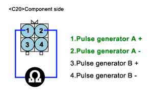
Measure resistance between terminal "1","2" of the "INPUT SPEED SENSOR" connector .
a.
Specification : 245 ± 30 Ω/20℃(68℉)
Ignition "OFF" .
Disconnect the "INPUT SPEED SENSOR" connector
Measure resistance between terminal "1","2" of the "INPUT SPEED SENSOR" connector .
Specification : 245 ± 30 Ω/20℃(68℉)
Is resistance within specifications?
YES
Go to "CHECK PCM/TCM " as below
NO
Replace "INPUT SPEED SENSOR(PG-A)" as necessary and Go to "Verification Vehicle Repair" procedure
Ignition "ON" & Engine "OFF".
Connect "INPUT SPEED SENSOR" connector.
Install scantool and slect a SIMU-SCAN,
Simulate frequency to INPUT SPEED SENSOR signal circuit.
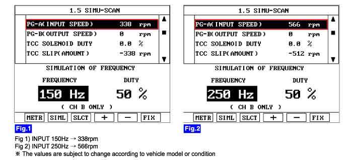
Is "INPUT SPEED SENSOR(PG-A)" signal value changed according to simulation frequency?
YES
Thoroughly check connectors for looseness, poor connection, bending, corrosion, contamination, deterioration, or damage. Repair or replace as necessary and then go to "Verification of Vehicle Repair" procedure.
NO
Substitute with a known-good PCM/TCM and check for proper operation. If the problem is corrected, replace PCM/TCM as necessary and go to "Verification of Vehicle Repair" procedure.
