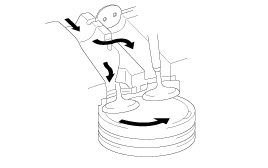
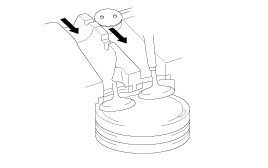
Item
Low and Middle Load
High Load
Engine speed
below 3000rpm
above 3000rpm
Valve operation
close
open
Description
illustration
Fail-safe
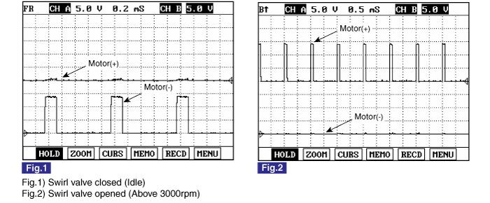
Variable Swirl Valve is opened fully
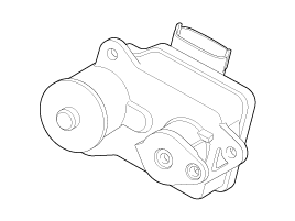
Variable swirl actuator consists of DC motor and valve position sensor which detects the position of swirl valve.
At idle and below 3000rpm, swirl valve is closed to take swirl effect. This swirl effect increases air flow rate.
Item | Low and Middle Load | High Load |
Engine speed | below 3000rpm | above 3000rpm |
Valve operation | close | open |
Description illustration |  |  |
Fail-safe | Variable Swirl Valve is opened fully | |
※ To prevent swirl valve and shaft from being stuck by foreign material and to learn max opening and closing position of swirl valve, it is always fully opened and closed twice at engine stop.
Item | Temperature℃(℉) | Resistance(Ω) |
Motor | 20 (68) | 3.2 ~ 4.4 |
Position sensor | 20 (68) | 3.44 ~ 5.16 |
Turn ignition switch OFF.
Disconnect Variable swirl actuator connector.
Check that swirl valve is stuck by foreign material.
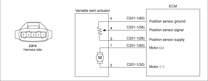
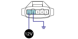
Supply the terminal 1 of variable swirl actuator connector (component side) with 12V and ground the terminal 2 of it.
Check swirl valve operation.
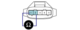
Measure resistance between the terminals 1 and 2 of variable swirl actuator connector (component side).
Resistence : 3.2 ~ 4.4Ω(20℃)
Measure resistance between the terminals 4 and 5 of variable swirl actuator connector (component side).
Resistence : 3.44 ~ 5.16Ω(20℃)

Disconnect the battery (-) terminal.
Disconnect the variable swirl actuator connector (A).
Remove the installation bolt (C) after removing the engine wiring harness part (B).
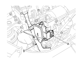
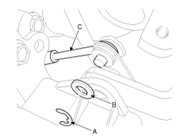
Remove the shaft link assembly (C) after removing the E-ring (A) and the washer (B).
Remove the variable swirl actuator.
Installation is the reverse order of removal.
Variable swirl actuator installation bolt:
9.8 ~ 11.8 Nm (1.0 ~ 1.2 kgf.m, 7.2 ~ 8.7 lb-ft)
Confirm normal operation of the actuator more than 3 times when the ignition switch OFF after full warm up (Engine Coolant Temperature > 70°C).