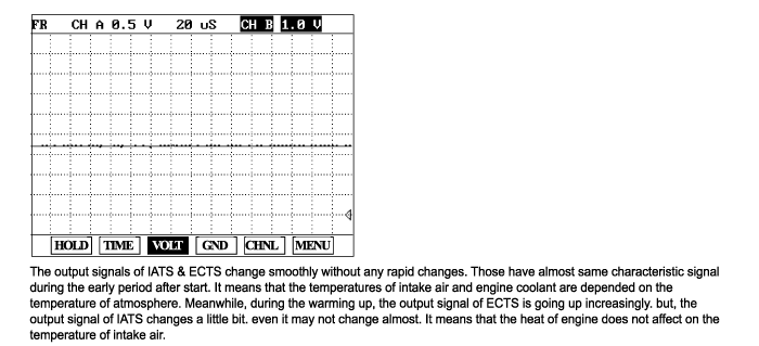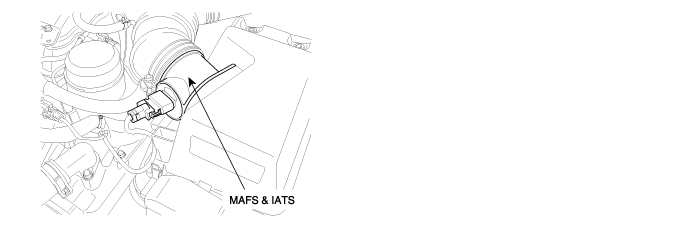
The Intake Air Temperature Sensor (IATS) is installed into the Mass Air Flow Sensor (MAFS). The IATS uses a thermistor whose resistance changes with the temperature. The electrical resistance of the IATS decreases as the temperature increases, and increases as the temperature decreases. The 5 V power source in the PCM is supplied to the IATS via a resistor in the PCM. That is, the resistor in the PCM and the thermistor in the IATS are connected in series. When the resistance value of the thermistor in IATS changes according to the intake air temperature, the signal voltage also changes. Using this signal, the information of the intake air temperature, the PCM corrects basic fuel injection duration and ignition timing.
PCM monitors difference between the startup coolant and IAT values.
If the difference between the startup coolant and startup IAT exceeds a maximum allowed value, PCM determines that a fault exists and a DTC is stored. MIL(Malfunction Indication Lamp) turns on when the malfunction lasts till consecutine 2 driving cycles.
Item | Detection condition | Possible cause | |
DTC Strategy | Case 1 | ● Skew Low Test: Monitors the difference between the startup coolant and IAT values | ● Poor Connection ● Open or short in harness ● IATS ● PCM |
Case 2 | ● Skew High Test: Monitors the difference between the startup IAT and coolant values | ||
Enable Conditions | Case 1 | ● Engine soaked time ≥ 360min ● Engine running state ● No disabling faults present ● IAT stored previous trip ● IAT Skewed Test Not Complete ● Startup Coolant Temperature >-20°C ● Airflow >15 g/s ● Vehicle speed >40kph | |
Case 2 | ● Engine soaked time ≥ 360min ● Engine running state ● No disabling faults present ● IAT stored previous trip ● IAT Skewed Test Not Complete ● Airflow >15 g/s ● Vehicle speed >40kph | ||
Threshold Value | Case 1 | ● Startup Coolant - Startup IAT ≥ 30°C | |
Case 2 | ● Startup IAT - Startup Coolant ≥ 20°C | ||
Diagnosis Time | ● Continuous (More than 1.25 second failure) | ||
MIL On Condition | ● 2 Driving Cycles |
Temp. (°C/°F) | Resistance (kΩ) | Temp. (°C/°F) | Resistance (kΩ) |
-40(-40) | 95.95 ~ 105.78 | 20(68) | 3.42 ~ 3.61 |
-20(-4) | 27.4 ~ 29.77 | 40(104) | 1.43 ~ 1.5 |
0(32) | 9.08 ~ 9.72 | 60(140) | 0.66 ~ 0.69 |
10(50) | 5.49 ~ 5.83 | 80(176) | 0.33 ~ 0.34 |