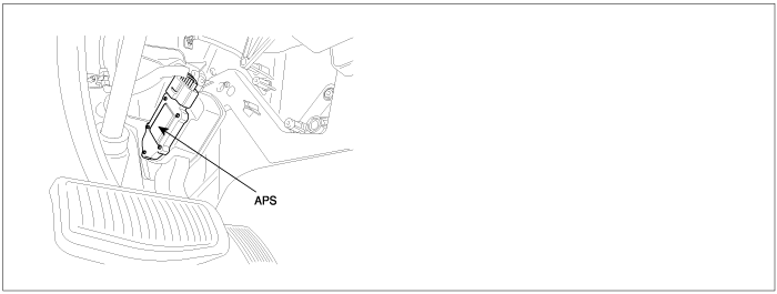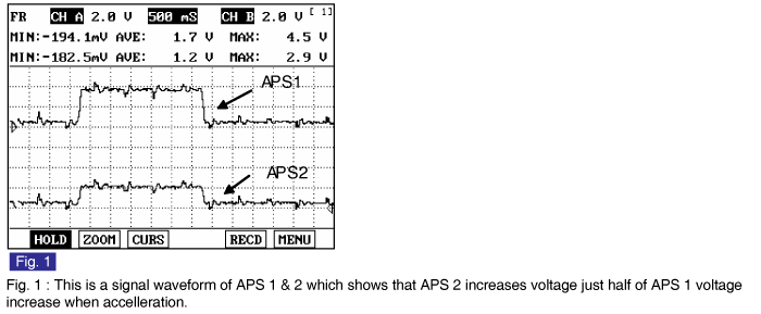

The Electronic Throttle Control(ETC) system is made of the components throttle body, Throttle Position Sensor(TPS) 1&2 and Accelerator Position Sensor(APS) 1&2. The APS is mounted in the accelerator pedal to detect the opening angle of the accelerator pedal. It has 2 sensors to detect the accelerator position and a malfunction of the accelerator position sensor. The PCM judges the current opening angle of the accelerator pedal from APS1&2, and the PCM controls the throttle motor based on these signals.
Checking output signals from APS 2, under detecting condition, if output signals are below the threshold, PCM sets P2127. MIL(Malfunction Indication Lamp) turns on when the malfunction lasts till 1 driving cycle.
Item | Detecting Condition | Possible Cause |
DTC Strategy | ● This code detects a continuous short to ground or open in either the circuit or the sensor | ● Poor connection ● Open or short to ground in Power circuit. ● Open or short to ground in signal circuit. ● Faulty APS ● Faulty PCM |
Enable Conditions | ● Ignition "ON" | |
Threshold value | ● APS2 < 0.125V | |
Diagnosis Time | ● Contineous (More than 0.18 sec. Failure for every 7.8 sec. Test) | |
MIL On Condition | ● 1 Driving Cycle |
Pedal Position | Output Voltage(V) [Vref = 5.0V] | |
APS1 | APS2 | |
C.T | 0.7 ~ 0.8V | 0.275 ~ 0.475V |
W.O.T | 3.8 ~ 4.4V | 1.75 ~ 2.35V |
