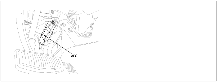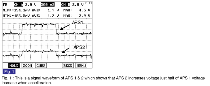

The Electronic Throttle Control(ETC) system is made of the components throttle body, Throttle Position Sensor(TPS) 1&2 and Accelerator Position Sensor(APS) 1&2. The APS is mounted in the accelerator pedal to detect the opening angle of the accelerator pedal. It has 2 sensors to detect the accelerator position and a malfunction of the accelerator position sensor. The PCM judges the current opening angle of the accelerator pedal from APS1&2, and the PCM controls the throttle motor based on these signals.
Checking output signals from APS 1 under detecting condition, if output signals are above the threshold, PCM sets P2123. MIL(Malfunction Indication Lamp) turns on when the malfunction lasts till 1 driving cycle.
Item | Detecting Condition | Possible Cause |
DTC Strategy | ● This code detects a short to high in either the circuit or the sensor | ● Poor connection ● Short to battery in signal circuit. ● Open in Ground Circuit. ● Faulty APS ● Faulty PCM |
Enable Conditions | ● Ignition "ON" | |
Threshold Value | ● APS1 > 4.5V | |
Diagnosis Time | ● Continuous (More than 0.18 sec. Failure for every 7.8 sec. Test) | |
MIL On Condition | ● 1 Driving Cycle |
Pedal Position | Output Voltage(V) [Vref = 5.0V] | |
APS1 | APS2 | |
C.T | 0.7 ~ 0.8V | 0.275 ~ 0.475V |
W.O.T | 3.8 ~ 4.4V | 1.75 ~ 2.35V |
